Power cords, a trip into the unknown!

amirm

Banned
Apr 2, 2010
15,813
38
0
Seattle, WA
pps. sheesh amirm...you really don't like my monitor...
I am trying to help you with your Christmas list ;) :).

JN, can you please explain a bit of your background for people who don't know it? I think it will provide a better context for where you are coming from and your knowledge base.
 

Steve Williams

Site Founder, Site Owner, Administrator
I am trying to help you with your Christmas list ;) :).

JN, can you please explain a bit of your background for people who don't know it? I think it will provide a better context for where you are coming from and your knowledge base.

For those of us who followed j_n elsewhere I agree that it would be helpful

Also j_n this quote of yours caught my attention and would love to know more

I have personally had the issue, figured out cause, effect, coupling, and solution
 

j_n

New Member
Nov 18, 2011
39
0
0
JN, can you please explain a bit of your background for people who don't know it? I think it will provide a better context for where you are coming from and your knowledge base.
Started my EE career in '81, as a young and totally ignorant EE, incapable of engineering my way out of a paper bag.

Since then, I've grown older.

A partial list...
Serious work experience with diodes from 3 inch diameter liquid helium types to 5 nanosecond recovery 3 amp devices, test, assembly...etc.
Serious work exp with epoxy impregnation of mil spec devices to superconducting antimatter confinement magnets.
Serious w.e. with every types of silicon chip ever fabricated up to the year 1986 , visual exam, troubleshooting, assembly, diebond, wirebond, test.
Not so serious (huge fun) exp with superconducting magnets, most for accelerators. Design, fab, and test.
Motion control, an 11 axis ultrasonic wiring machine for super magnets..7k lines of VB code so far..
Soldering of all types, gobs of tin/silver experience.
I've also played with audio stuff for hobby and work back in the day....'78 to '90

My most interesting experience? Troubleshooting a 12 bit variable conversion speed ADC at the chip level via a metallurgical scope at 400x with a coupla o-scopes as well, without benefit of a schematic or a chip diagram..with two gentlemen in blue suits and bulges in their jackets watching me. (with hairnets on, supreme giggle factor had they not been next to me). The funny thing was it was classified, yet I had already worked with the chips 2 years earlier.

Cheers, jn
 

j_n

New Member
Nov 18, 2011
39
0
0
Also j_n this quote of yours caught my attention and would love to know more

I was running a pair of swtpc 250's into a pair of K's. Turned out that the system was marginally stable, and depended on what I used as a power cord and how I layed it out. Turned out that the amplifier power draw was sufficient to generate ground loop currents between the power amps and the source component.

In troubleshooting the system, I found that by changing the cord, I was able to remove the vast bulk of the problem. Turned out that the origional cord I used was a flat conductor type, built exactly like romex is configured. This produced a net magnetic field around the cord, and roughly half that field was available to go through the ground loop of the system.

There was also a ground current susceptibility built into the tigersaurus. By isolating the rca's from chassis ground, I removed most of that. Since then, I learned how to remove it all by judicious design.

Of course, now that they are ground current impervious, I don't use em...sigh. most of my good stuff is gathering dust in the basement..

Cheers, jn
 

garylkoh

WBF Technical Expert (Speakers & Audio Equipment)
Sep 6, 2010
5,599
225
1,190
Seattle, WA
www.genesisloudspeakers.com
I happen to have run a spice simulation of typical power amplifier supply, feeding two constant +-20amp loads (feeding the amp output stage). It nicely shows this effect:

Thanks, Amir. You're the spice-master :)

Power supply design is quite fascinating - backwards towards the wall - resulting in IMHO a power cord possibly making a difference to the sound quality. I'm glad that I'm not the only one on this forum that thinks this way.

Amir, if you are willing to do some modeling - use half bridge rectification on the model and you should see the "haversine spike" (I don't know what it's called) get larger.

Reduce the current load while keeping the same capacitance, and see what it does. Get down to 1 amp, and then increase capacitance. Model with ESR on the capacitors.

What would become really interesting is if spice can put a single impulse load into the model. Say a piano note and then see what the power supply does. When I get some time, I can also do the same but with an oscilloscope and match what we see with what we can model.

Unfortunately, there will still be those here who will say that we can measure it, but we won't be able to hear it..... but this being WBF, at least it won't be a waste of time :D
 

amirm

Banned
Apr 2, 2010
15,813
38
0
Seattle, WA
Thanks, Amir. You're the spice-master :)

Power supply design is quite fascinating - backwards towards the wall - resulting in IMHO a power cord possibly making a difference to the sound quality. I'm glad that I'm not the only one on this forum that thinks this way.

Amir, if you are willing to do some modeling - use half bridge rectification on the model and you should see the "haversine spike" (I don't know what it's called) get larger.

Reduce the current load while keeping the same capacitance, and see what it does. Get down to 1 amp, and then increase capacitance. Model with ESR on the capacitors.

What would become really interesting is if spice can put a single impulse load into the model. Say a piano note and then see what the power supply does. When I get some time, I can also do the same but with an oscilloscope and match what we see with what we can model.

Unfortunately, there will still be those here who will say that we can measure it, but we won't be able to hear it..... but this being WBF, at least it won't be a waste of time :D
I will work on it. For now, the caps do have ESL and ESR in them (100nh and .01 ohms respectively). When I said it is an ideal circuit I meant in that it assumes there is infinite power available and such.
 

DonH50

Member Sponsor & WBF Technical Expert
Jun 22, 2010
3,968
329
1,670
Monument, CO
Amir, you need to add some RLC to model the power supply a bit better... That will reduce (and prolong) the current spikes. Of course, when you start adding capacitor models (not just ESR, the whole RLC bit), things get worse...

Gary, SPICE can put in an impulse (close enough, especially at audio). I have had to make my package and supply models match reality many times through the years; sometimes it is easier than others.

General SPICE note: if you really start looking 16+ bits down, you are going to have to tighten up your tolerances and probably change the convergence routines or you'll be seeing strange simulation noise/artificats. I'd tighten things like ABSxxx and RELxxx by 2 - 3 orders of magnitude and force Gear-only; you may also have to limit the max timestep (I had to do that even for the simple cable sims I did earlier). I doubt this is needed for the power supply sims, however, but you are covering a wide dynamic range when you start digging deeper into the influence of the supply on the rest of the circuits.

JN -- SWTPC, that's a name I have not seen in ages! I built a few kits for friends but never actually owned one. As for radiated fields, most any sound guy can attest to the impact a power cable can have on a long mic run. However, once switching to a shielded power cable and/or putting more space between power and signal runs, I am not sure upgrading from the shielded power cord to something esoteric (and costing 10x the price) really matters. Rarely done any sort of experiments, however. I have not really considered the magnetic field, either, hmmm... Hate it when folk force me to think! :)

Now back to your regularly-scheduled power cord debates... - Don

p.s. Was typing and Amir beat me to the post... Any series R and/or large chokes in the power supply (voltage source) to model it's bandwidth? Most power supplies are effectively open circuits by a few hundred Hz if there is no filtering... Or are you modeling the transformer as well?
 

garylkoh

WBF Technical Expert (Speakers & Audio Equipment)
Sep 6, 2010
5,599
225
1,190
Seattle, WA
www.genesisloudspeakers.com
I will work on it. For now, the caps do have ESL and ESR in them (100nh and .01 ohms respectively). When I said it is an ideal circuit I meant in that it assumes there is infinite power available and such.

Oh good! What size caps? The usual ones I see in power supplies that are 5,600uF 100V types typically have ESR 2 to 5 times that.

The Panasonic T-UP 39,000uF 80V that I use was one of the lowest at 0.013 ohms. But that is huge, and something this large isn't common.
 

j_n

New Member
Nov 18, 2011
39
0
0
JN -- SWTPC, that's a name I have not seen in ages! I built a few kits for friends but never actually owned one. As for radiated fields, most any sound guy can attest to the impact a power cable can have on a long mic run. However, once switching to a shielded power cable and/or putting more space between power and signal runs, I am not sure upgrading from the shielded power cord to something esoteric (and costing 10x the price) really matters. Rarely done any sort of experiments, however. I have not really considered the magnetic field, either, hmmm... Hate it when folk force me to think! :)

They were great. 125 dollars for the 250 tiger kit. I built 8 of them.

It was line level where I had a problem. Since it was related to the line cord choice of construction, and the input ground reference layout of the amp, I fixed both and had no further issues.

For a 125 foot unbalanced run, I solved the problem by wrapping the IC around the line cord. It reduced the loop area. The only caveat is that the twist pitch of the wrap cannot match the line cord twist pitch.
cheers, jn
 

j_n

New Member
Nov 18, 2011
39
0
0
Ah, where's my manners. First pics from me, be gentle, I'm learning here...text to follow if I'm lucky..

Aha...pdf's don't open immediately..good to remember..

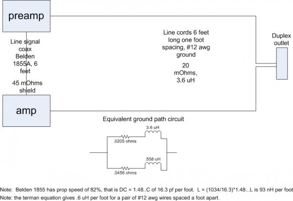
First pic is the derivation of the ground path any current from the source takes in returning to the source. One would think that all the current being sourced into the IC would go back via it's shield. If you look the ground return path is two paths, one being the braid, the second being the safety ground. Note that at DC, 2/3rds of the current returns through the ground path. At some frequency, half the current will be in the IC shield, and at high frequency, it is all in the shield.

For a shielded conductor to work, ALL the return current MUST be through the shield. And, the centroid of the send current in the core must be in the exact same location in space as the centroid of the shield return current..If not, the run is susceptible to external magnetic field influences. Note that for a twisted pair in shield, neither wire has a common centroid with respect to the shield, they share a common distributed centroid, and the pair does indeed share a common centroid with the shield.

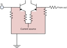
The second pic depicts the most sensitive spot in an amplifier. Any time varying magnetic field which can go through that loop will be amplified at the full open loop gain. If the internal layout of the amplifier is such that ground loop currents go near that shaded area, coupling is a distinct possibility.

The third is an overall pic of a source and amp with a duplex outlet. I've shown the areas where the bulk of the coupling can occur. It is important to understand the frequency based proportionality of some of the couplings. Effects which are trivial at 60 hz may not be so at 6 Khz when proportionality is frequency squared.

Cheers, jn
 

Attachments

  • ground loop calc&#117.jpg
    ground loop calc&#117.jpg
    93.6 KB · Views: 119
  • input pair..jpg
    input pair..jpg
    11.2 KB · Views: 113
  • Ground loop..pdf
    23.9 KB · Views: 101
Last edited:

microstrip

VIP/Donor
May 30, 2010
20,807
4,704
2,790
Portugal
j_n,

We should remember that some manufacturers ground their amplifiers through a 10-100 ohm resistor, a low resistance coil or back to back connected diodes, all of them sometimes bypassed by capacitors , avoiding or reducing the EMF induced ground current and the noise effects due to ground loops. These techniques would drastically change the equivalent ground path circuit.
 

j_n

New Member
Nov 18, 2011
39
0
0
j_n,

We should remember that some manufacturers ground their amplifiers through a 10-100 ohm resistor, a low resistance coil or back to back connected diodes, all of them sometimes bypassed by capacitors , avoiding or reducing the EMF induced ground current and the noise effects due to ground loops. These techniques would drastically change the equivalent ground path circuit.

Totally agree. The safety problem is...in the event of a hot to chassis short within the chassis, what happens with the resistor? a 10 ohm resistor will cause 12 amperes at the breaker, which will not cause the breaker to clear. This leaves a chassis hot at the level of 120 volts forever, or perhaps for the rest of your life..which would probably feel like forever..

100 ohm is even worse.

Back to back diodes do work, but the problem with that is the issue of how the diode handles the surge, and if it fails, will it remain contained or will it open.

Take a 35 ampere diode bridge in an aluminum case and potted. there are two basic designs out there, one where the silicon die is perpendicular to the mounting surface, and one where it is parallel. If the parallel version is subjected to a fault current which causes the die to explode, the side walls of the bridge will not hold it in, ejecta will go out and the die will fail open. Should this occur, the chassis will probably remain hot.

If the die is perpendicular, the aluminum side walls will contain the forces until the silicon can melt and fuse into a low impedance mass. This scenario should allow the breaker to clear.

The only real alternative for the diodes is to use diodes capable of the bolted fault current of a short to chassis. Those are some honkin diodes however.

Cheers, jn
 

microstrip

VIP/Donor
May 30, 2010
20,807
4,704
2,790
Portugal
Totally agree. The safety problem is...in the event of a hot to chassis short within the chassis, what happens with the resistor? a 10 ohm resistor will cause 12 amperes at the breaker, which will not cause the breaker to clear. This leaves a chassis hot at the level of 120 volts forever, or perhaps for the rest of your life..which would probably feel like forever..

100 ohm is even worse.

Back to back diodes do work, but the problem with that is the issue of how the diode handles the surge, and if it fails, will it remain contained or will it open.

Take a 35 ampere diode bridge in an aluminum case and potted. there are two basic designs out there, one where the silicon die is perpendicular to the mounting surface, and one where it is parallel. If the parallel version is subjected to a fault current which causes the die to explode, the side walls of the bridge will not hold it in, ejecta will go out and the die will fail open. Should this occur, the chassis will probably remain hot.

If the die is perpendicular, the aluminum side walls will contain the forces until the silicon can melt and fuse into a low impedance mass. This scenario should allow the breaker to clear.

The only real alternative for the diodes is to use diodes capable of the bolted fault current of a short to chassis. Those are some honkin diodes however.

Cheers, jn

I should have written more carefully - I think manufacturers ground the chassis, and only connect the 0V signal line through the grounding network, reducing risks. In order to do this they must insulate the audio connectors ground from the chassis.

Differential protection is now mandatory in most countries in Europe - if any ground current exceeds 30 or 300 mA, the breaker will immediately shut-off mains,
 

mep

Member Sponsor & WBF Founding Member
Apr 20, 2010
9,481
17
0
I have a question for you all. I have a dedicated 20A outlet per Krell’s recommendation for my KSA-250 power amp. I have a small amount of hum/buzz that you can hear from the amp itself as well as through the speakers. When I first contacted Ray at Krell, he said to make sure I had the KSA-250 at least 2’ away from the power supply for the KBL preamp (which it wasn’t). So I moved the featherweight KSA-250 out in the room between my speakers. The hum/buzz was reduced, but not eliminated. Now, the PC I’m using is a PS Audio cord and the only one I currently have that is rated for 20A (Krell was supposed to send me a 20A cord when they returned the KSA-250, but they forgot. Ray told me today he would send one to me.).

So anyway, I hate the way the female end of the PS Audio PC fits into the KSA. It does not make a nice tight fit. Instead, the female end sags (from the weight of the connector?) and hangs down. Ray says he thinks the hum/buzz is because the amp is not getting enough current through the PC. Does this sound plausible? If I can eliminate that hum/buzz, I will be one happy camper.
 

j_n

New Member
Nov 18, 2011
39
0
0
I should have written more carefully - I think manufacturers ground the chassis, and only connect the 0V signal line through the grounding network, reducing risks. In order to do this they must insulate the audio connectors ground from the chassis.

Ah yes, that is different. IIRC, this requires there be no possibility that an internal fault can cause external surfaces to become hot. Akin to the double insulated two prong devices.

Ya know, if the demand for input balanced transformers were large enough, I bet they could become cost effective to use, get rid of all this unbalanced garbage.

Differential protection is now mandatory in most countries in Europe - if any ground current exceeds 30 or 300 mA, the breaker will immediately shut-off mains,

Ah, Equipment ground fault interrupter. On this side of the pond, that does happen in the industrial stuff, if I recall somewhere around 50 milliamps but adjustable. The best we do at the moment is the 4 to 6 mA GFCI. (unit must not trip at 4 milli, unit must trip at 6.)

Um, a safety point: One of my friends (yes I have a few thank you!!) is a master electrician, and he stated that about 5% of all the GFCI's he installs out of the manu's box....fails immediately, does not trip. Anybody buying or using them, be careful to test them after install..

Cheers, jn
 

j_n

New Member
Nov 18, 2011
39
0
0
So anyway, I hate the way the female end of the PS Audio PC fits into the KSA. It does not make a nice tight fit. Instead, the female end sags (from the weight of the connector?) and hangs down. Ray says he thinks the hum/buzz is because the amp is not getting enough current through the PC. Does this sound plausible? If I can eliminate that hum/buzz, I will be one happy camper.

My first thought is no.

My second is, try moving the IC's around. I've solved problems by actually twisting the ic's around the power cords ( although my example of 125 foot cords is kinda extreme).. Think of the IC's and power cords as defining a loop in space, and that any magnetic fields in the area that are able to go through that loop can make noise. If you reduce that physical loop size, you reduce the amount of magnetic field that can go through it.

Almost everybody I hear tends to say that power cords and IC's don't mix, keep em apart, keep em 90 degrees... None of that is correct... another windmill for me to tip at...:D

Cheers, jn
 

mauidan

Member Sponsor
Aug 2, 2010
1,512
11
36
Pukalani, HI
So anyway, I hate the way the female end of the PS Audio PC fits into the KSA. It does not make a nice tight fit. Instead, the female end sags (from the weight of the connector?) and hangs down. Ray says he thinks the hum/buzz is because the amp is not getting enough current through the PC. Does this sound plausible? If I can eliminate that hum/buzz, I will be one happy camper.

Put some tape or heat shrink on the female connector so it fits tight and use something to support the weight of the PC.
 

mep

Member Sponsor & WBF Founding Member
Apr 20, 2010
9,481
17
0
My first thought is no.

My second is, try moving the IC's around. I've solved problems by actually twisting the ic's around the power cords ( although my example of 125 foot cords is kinda extreme).. Think of the IC's and power cords as defining a loop in space, and that any magnetic fields in the area that are able to go through that loop can make noise. If you reduce that physical loop size, you reduce the amount of magnetic field that can go through it.

Almost everybody I hear tends to say that power cords and IC's don't mix, keep em apart, keep em 90 degrees... None of that is correct... another windmill for me to tip at...:D

Cheers, jn

So I'm using balanced ICs. You think I should wrap both of them in a small loop around the PC?
 

About us

  • What’s Best Forum is THE forum for high end audio, product reviews, advice and sharing experiences on the best of everything else. This is THE place where audiophiles and audio companies discuss vintage, contemporary and new audio products, music servers, music streamers, computer audio, digital-to-analog converters, turntables, phono stages, cartridges, reel-to-reel tape machines, speakers, headphones and tube and solid-state amplification. Founded in 2010 What’s Best Forum invites intelligent and courteous people of all interests and backgrounds to describe and discuss the best of everything. From beginners to life-long hobbyists to industry professionals, we enjoy learning about new things and meeting new people, and participating in spirited debates.

Quick Navigation

User Menu

Steve Williams
Site Founder | Site Owner | Administrator
Ron Resnick
Site Co-Owner | Administrator
Julian (The Fixer)
Website Build | Marketing Managersing