1704 matching
So finally, my large post. It has been updated many times (was originally written a week ago) to hopefully reflect best what's all happening. I'm praying a bit that because of the so many changes it is still consistent and without toooo many typos.
It all started out with below two quotes, Phasure needing some "defence". However, I tried my best to make it educational.
And you know what ? my personal reasoning about this all ends up with the conclusion that the Trinity should sound best. However, this is form one angle only and there are "Trinity more". So read on.
Hi Elberoth.
The
Phasure NOS1 USB dac seems to use much of the same tech as the Trinity. Eight x PCM1704 and completely filterless (analogue or digital) running femto clocks. The Phasure relies on the computer software to upsample to 705 or 768 and to apply a special Arc prediction filter that eliminates pre and post ringing (called impulse response in the Trinity manual) which takes all of this processing out of the dac which improves dac clock behaviour.
When I read the description of the sound of the Trinity dac I thought that it was exactly how most of us Phasure owners would describe the sound of our dac: that it has no sound of its own. I am quite sure that the designer of the Phasure does not pick the cream from his crop of PCM1704s Like for the Trinity) and it's unusual shape and presentation do manage to keep costs down so it is a fraction of the price of the Trinity, but I sure would love to hear them both side by side one day.
A 6moons review of the Phasure NOS1 USB is
here.
Merry Christmas,
Anthony
Edit: I just love that these old dac chips when implemented properly can be used to beat more modern sigma-delta chips...and that they really do make DSD redundant.
Anth,
I'm glad you like your DAC. I bet it sounds great. There are some similarities between those DACs (namely low phase noise clocks, 1704 DACs, USB input), but as they say - the devil is in the detail.
There are the following basic differencies:
Phasure uses only 8 PCM-1704 DACs vs 16 in the Trinity.
The DAC chipsets used in Phsure are not hand selected (read: have higher THD).
Phasure doesn't use the innovative time-staggered arrangement, but runs them in a common parallel arrangement (with inputs and outputs of all DACs are interconnected).
Phasure DAC uses 16x up/oversampling, where Trinity - thanks to said time-staggered arrangement - gets equivalent of 64x.
Trinity has even better clocks.
The Phasure describes the DAC as filterless design (non oversampling), but the truth is, that they had only moved the filtering from the DAC itself to computer software - they call it Arc Prediction upsampling and filtering.
Ok, surprise ...
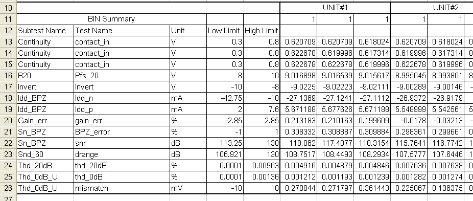
Might someone recognize this ... These are official TI measurements.
So what I do (or have been doing) is pre-selecting, say, "double K" (grade) batches. And already for many years you won't be able to obtain those (way) better batches anymore; So there's a difference between K grade and K grade. And too bad I have those double K batches ...
There's a LOT to this, but I'll try to give a few examples that may explain things somewhat.
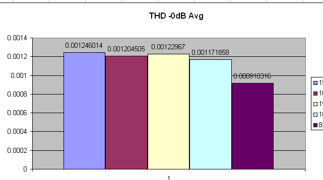
What you see here is 4 of the poor batches (though grade K !) and the rightmost one is a good one. This counts for the pictures below all the same (the purple bar always in the right hand side is about batches we use).
This one is about THD at -0dBFS (full scale output). So the purple averages to 0.00091% while the others show around 0.0012; this is around 2.5dB worse.
Notice in between : While this thus are the officialy TI measurements which also determine "K grade or not" (see table above and the two "Limits" columns), for the NOS1 0.00043% THD+N is achieved. So, over 6dB better than the specs of the chips are. And just measured at the normal outputs, meaning even at the end of a 2m interlink.
And no, the chips are not just parallelled, because it is a fully differential setup (this already needs 2 chips per channel). And some more (plus more about this below).
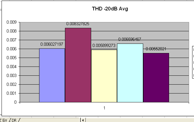
This one is crucial;
It shows the fairly regular standard of measuring D/A chips at -20dB. Look what happens to the second batch shown; It is way above the others, with the notice that this is the average of many chips. So, while average, individual chips will be worse again. Look in the table at line 24 and you see that Unit#2 is close to 6dB worse here compared to Unti#1 (and notice that the measurement of each chip is performed 3 times - that's why the 3 columns).
So, the one chip is 6dB worse over the other ? so what. Well ... if we realize that this is at -20dBFS (and which is just comparable to samples playing at that level) which is just a randomly chosen "level" with 10s of thousands other levels in between that -20dBFS and -0dBFS, we can see how unlinearity plays a role here. BUT it is way way worse, because TI selects the chips (for K grade but also on not failing all together) on just these two output levels for THD.
Looking at the table again, you see the threshold of 0.00963% for the -20dBFS test. This means that chips which show 0.00962% pass the test for K grade. Now, what TI does not understand (or doesn't want to admit) is that e.g. -19dBFS or -14dBFS etc. the most easily can show 0.012% THD. Notice : The higher the output the better THD should be. However unlinearity depicts that this can/will be worse for some combination of resistor settings (this is all about resistor matching) no matter the level is higher. Point is : that 0.00963% threshold is way too low (should be 0.006% or so) in order to let behave the higher levels better than the real threshold (which is allowed to be 0.00963% again). Too difficult to explain ? Well, just read on, you may get the idea from other angles.
With R2R chips all is about the linearity of them. This is about the resistors in there and how equal they all are. So, if they all would be 100% equal it won't matter which combination of resistors is "dialed in" because the result would be a linear voltage if all the combinations (say from the lowest output value to the highest) would be plotted. If, for simplicity, you look at how the digital code works, with 0000 being decimal 0, 0001=1, 0010=2, 0011 = 3, 0100=4, 0101=5, 0110=6, 0111=7, 1000=8 and so on - and supposed decimal 1 is 1mV, 2=2mV, 3=3mV and so on, then 1,2,3,4,5,6,7 etc. subsequently must add exactly 1mV to the output signal (it is current for the 1704 but never mind - that ends up in Voltage anyway). Now supposed that each resistor represents such a bit and the second resistor is off by 10%. So, the 0010 is off. That adds 1.1mV instead of the intended 1mV. Now look back in my little row where the 0010 is used. This is in 2, 3, 6 and 7. So 2 will show 2.2mV (just do decimal 2 + 10%), 3 shows 3.2mV (2.2 + 1), 6 shows 6.2mV and 7 shows 7.2mV. Total sequence : 0, 1, 2.2, 3.2, 4, 5, 6.2, 7.2. This already looks quite messy with only one resistor being off, while actually all are, to some extend.
What I just know (because of so many tests) is that the closer the chips are to the TI thresholds the less match the resistors. This can just be taken as a rule. So, the chips we use (the purple bars) always and ever show the same results up to 0.0005% at whatever level we try them. Practically, for 16/44.1 material and -0dBFS this shows for Left/Right something like 0.00183%/0.00188% (difference is mentioned 0.005%). Next DAC could be 0.00187%/0.00184%. Lowering the level with e.g. 6dB could show 0.00210%/0.00204%. Keep in mind that this is not really about the set output level, because when a signal is produced all resistors will activate/deactivate because of the nature of the sine test signal (which crosses zero, goes up to max, goes down again etc.). Point is : this is all totally stable.
But now the bad batch (remember, still K grade and looking at the plots above not *that* much wrong with them) :
DAC output now can show 0.00200%/0.00700%. Wow. So now suddenly the right channel is ~11dB worse on THD. Now I attenuate the signal with 6dB and it's 0.01000%/0.00400%. And, before you think this is about dropped bits, when I attenuate 0.5dB it could show 0.01100%/0.00500%.
Yeah, just compare the sequences and you see it is really a mess now.
There is no single way these chips can be selected for individual matching or anything. With the good batches yes, but now there is no matching needed; they just all behave the same and otherwise it is beyond measurement (THD and noise measurement).
Think of it; A genuine differential setup in the digital domain uses two chips (at least) to form the plus and minus signal (better : the opposite signals). But now these opposite signals, meant to cancel common mode noise, are never the same. So, what additionally happens (apart from the noise cancellation not working anymore) is that the resulting signal (which can be regarded the sum of the both individual signals) receives an additional deformation. Not that TI ever said that we should form a differential setup out of some 1704's ...
No worries for Trinity customers : The Balanced outputs in there will be "generated" so to speak. So, after the D/A conversion the signal is split into a plus and minus opposite component (usually through OpAmps) and the described phenomenon is now not in order. The net result on balanced outputs depends on "the whole package" and not for me to judge. Theoretically though a part of the signal is now not subject to common mode noise rejection (so more noise) while the "differential outputs" will be not suject to the 1704's unlinearity (so there it will be better in common mode noise rejection, assuming injected noise after the D/A conversion).
Additionally, when I put in a set of those "bad" chips in the Phasure NOS1 its (audible) accuracy is totally lost. Mind you, when measuring this at -0dBFS and perceived "chip matching" has taken place from a "bad batch" and it shows 0.00210%/00210%, this still is the case (does not sound accurate) because all we could do is match the chips for that one level (-0dBFS) while attenuating the test signal shows its unlinearity right away.
Maybe Dietmar likes to comment or just express his thinking regarding what I'm all saying here. It is also about batches of the 1704 which should have been produced in 2008 or earlier (Phasure has all of those as obtained in 2010).
Please notice that outside my own general interest in the 1704 (which is a hell of a thing to work with - different to what Dietmar seems to say about it) this all was also a response to this :
The DAC chipsets used in Phsure are not hand selected (read: have higher THD).
Emphasis is mine now and I hope I could justify it somewhat.
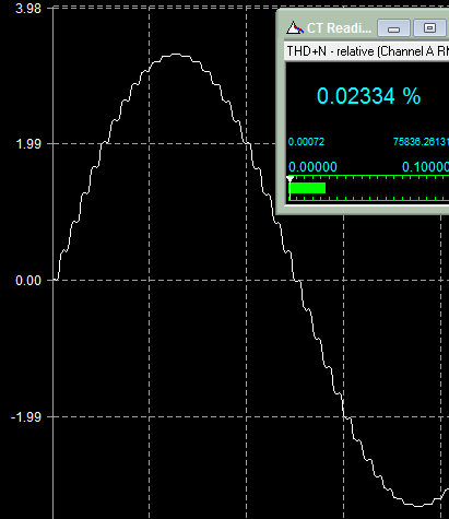
Native signal.
The above two are just for reference for Dietmar, with the explicit notice that
a. this is the 24/44.1 test signal from Trinity's website, upsampled filtered through XXHighEnd (16x), measured at the end of 2m XLR interlinks.
b. this FFT is 128K and 16 times averaged.
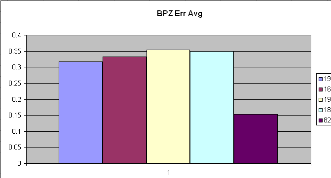
This one is interesting, especially when combined with the next Excel graph (2nd pic below). First off, this is part of the proof (to myself) that TI can't produce the 1704 anymore as they ever did (besides that I am sure they aren't even produced anymore but that's another matter). This is what's called the "bipolar zero error" and TI's solution to minimize the "glitching". Glitching is the jump from all resistors being active to all not active and which is related to the "2s complement" C code where going from positive to negative in binary and the other way around (say from decimal +1 to decimal -1 and in binary it looks like 00000001 - 11111110. So, now suddenly all the bits "flip" and in the chip this means that there's a high current implied to let it do this. Here you see this happening, though from another chip :
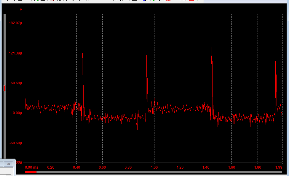
Watch out, because this is low level (IIRC -108dBFS) and the peaks themselves are also of fairly low voltage (like 181uV) but way more high than from the 1704. Another thing to watch out for is the low inherent noise which is something like less than 1uVRMS. Now envision the system noise to be around 30uV p-p (peak to peak) *and* envision the 1704 to do better than you see above. So what happens ? the glitching energy (anomaly) disappears in the noise.
Now back to the plots above ... and see the difference with my selected batches and the ones which I rejected. A difference of over 6dB. To understand what's happening, now look below :
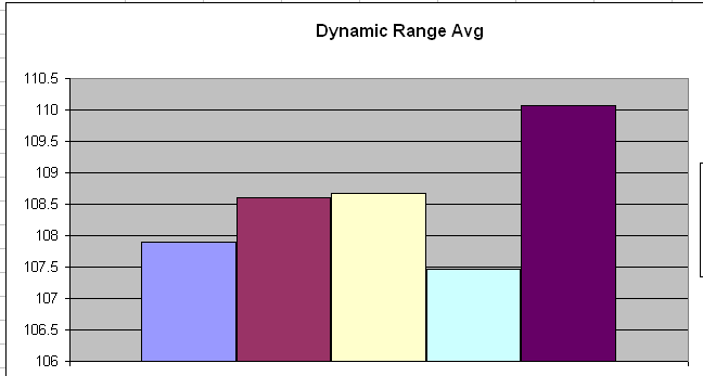
Aha. But *that*'s a difference ! So what you actually see here is that the difference in noise (a deviate from dynamic range in this case) is over 3.5dB worse for the worst batch. Partially this is caused by the glitching energy (which is half wave cycle noise - see picture above at each spike (this is 1KHz)) and partially this will be caused by the unlinearity happening in the least significant bits/resistors (those which control the lowest output values).
The fun of this all is that in both the case of the good batch and the bad batch, the glitching energy can not be seen because they both disappear in the noise of the 1704 itself. I don't have a picture of a bad batch, but if you want you can
look here - but scroll to the very bottom and the subject "24 bit resolvement". Or please don't go there at all when you feel it is inappropriate (it is my own forum).
Anyway, this is about how any R2R chip is subject to its own "resistor switching noise" or glitching. And you don't need to go there at all as long as you believe me that (indeed) the selection of the best D/A chips is crucial because when they exhibit more noise they will resolve less (bits).
(It is not the same subject as "unlinearity" as such and to me it shows that today that the latter batches of TI have been produced in a different fashion (plus I know that they set up a new factory with many difficulties).)
What you might also see in there is that while the chips of the good batches officially (by my own measurement that is - TI spec for K grade is 106.921) have a dynamic range of just over 110dB, this can be better than 120dB per "better implementation" (remember the "whole package thing"). So :
but runs them in a common parallel arrangement (with inputs and outputs of all DACs are interconnected).
Sorry, but not correct either.
Phasure uses only 8 PCM-1704 DACs vs 16 in the Trinity.
Even that is not correct since the NOS1 can be shipped with 16 chips just the same (Anthony, look in your Specs document). But whatfore ? It adds something like 800 euros to the price to bring what ? about NOTHING. How ? Well, it should add another 3dB of dynamic range and the resolvement of a next bit needs 6dB (which in my case would lead to a possible 23rd bit which is so much surrounded with noise that I personally don't advise to spend that money to anyone).
Phasure doesn't use the innovative time-staggered arrangement
True ! But as a DAC designer one can think about what this really brings. Remember, "whole package" thing again ! So, while what LIANOTEC does here is linear interpolation of the simplest form (please read this as "won't imply the best THD possible" and "more linear than formal linear because LIANOTEC will be "right in the middle of two samples" -> Dietmar, correct when needed !) - this ... hey, doesn't matter much. Read : It doesn't matter whether this can be theoretically better so it's all right.
Oh ?
Yes, in my view whether THD could be better by other means, at these higher frequencies it is not about that anymore. And now let's hope it doesn't get too complicated ...
"Interpolation" as such is about two phenomena : 1. Brickwall filter (minimize the HF incurring stepping energy) and 2.
Reconstruction of the analog wave.
Ad 1.
Being right in the middle of two original samples (LIANOTEC) is OK for this *IF* reconstruction happened first and when this is needed (this is for sure needed for 44.1 (or 48) material with the wise decision of Trinity to take this one step higher and apply it up to 96KHz).
Ad 2.
Reconstruction is about the too few available samples to represent the higher frequencies. So, that only 4.x samples are available to represent a 10KHz sine (the higher the frequency the less samples available). It looks nasty and it sounds so (but genuine NOS lovers will find this okay).
Thus, what needs to happen is that first the best sine needs to be made from that nasty wave shape (named "reconstruction") and after that we can apply the brickwall filter at best means (but in practice (or normally) this is the same stage in the process)).
Since reconstruction is about sheer low pass filtering which hammers upon the time domain or in other words : where making the frequency domain better (nice sines) is traded in for the time domain (ringing = smearing), this thus rings. Nothing to do about that when sheer filtering is applied.
Do notice : This reconstruction / filtering happens in the digital domain. It is totally unrelated to the left overs from the brickwall filtering, meaning that no matter how small, HF will remain of that and the smaller the stepping, the more upwards in the frequency spectrum the HF left overs are shifted to.
LIANOTEC does this (for the possible good reason of not harming amplifiers).
Are we there now ? ... almost;
For those who like to compare theories (and I sure do), we need to compare what Trinity does for real practice with how Phasure NOS1/XXHighEnd does it. And please remember, it was for a reason that I said that only one manufacturer could be interested in how Trinity does it. So :
Phasure :
Reconsructs in the digital domain in lossless fashion (meaning that the original wave can be rebuild out of the reconstructed wave) which does this per means of "Arc Prediction" and it takes along the brickwall filtering. Upsampling needed for this is 16x. HF noise *only very close to the nyquist limit* (which means say 20KHz with the limit of 22.05KHz for 44.1K sampled material) will exhibit at max 3dB down close to 352.8KHz (which is the nyquist limit after upsampling). At e.g. 16KHz the HF out of band leftovers are 60dB or more down. Also : HF in-(audio-)band energy is way less than the lower frequencies to begin with; amplifiers won't burn (and speakers neither).
No analog filter is applied.
It exhibits zero ringing.
Trinity (sorry, but I use 16/44.1 Redbook again) :
Reconstructs in the digital domain by means of 8x oversampling in the mean time applying the necessary low pass filter and the audio band will be (or should be) completely free of harmonic anomalies. Further story as above is exactly the same, but now close to 176.4KHz (read : the reconstruction can't do better because of 8x oversampling only so it is the not complete reconstruction which exhibits this).
Ringing will be 8 samples only (pre- and post as seen from Trinity pictures (meaning phase linear hence FIR filter)).
Now LIANOTEC jumps in, and this does *not* shift this incomplete reconstruction further into the high frequency band.
Dietmar : I think I am correct here, so please correct when needed !
What LIANOTEC does though is further improvement on the brickwall filter (making the stepping 8x smaller again) which IMO will not be measurable for in band THD. What it does (I estimate) is only decreasing the 3rd haronics of the stepping itself (like Trinity's pictures show BUT they are from 384K sampled files !) but these are not the same "harmonics" as the left overs of the incomplete reconstruction (notice : "complete" reconstruction implies infinite oversampling and infinit ringing).
Even when I am correct on this one (and I am NOT sure) then does this matter ? NO. To me it doesn't because this is my design (as a major part of the whole package) and I apparently chose for that and thus don't care (with the explicit reasoning of high frequency (in band) energy being less anyway and such).
So which will sound better (and sorry to work with theories only hence with measurements) ?
For Hires it will be the Trinity.
For Redbook decide for yourself but realize that this is the debate "NOS vs OS". This in other words : Time domain vs Frequency domain. One thing : The Phasure combo (DAC+Software) improves vastly on the "NOS" frequency domain while leaving the time domain 100% in-tact. This is not subjective but just measureable. So what I can say for sure is that when compared to genuine NOS the Phasure is (measurement wise) infinitely better, while sustaining all NOS characteristics (compare the little graph more above denoted "Native signal" with its 0.02334% THD+N vs 0.00059% THD+N and which is only at 1KHz ! (read : higher frequencies show a way larger difference).
In a previous version of this text I ended with the question "But there is a secret left, guess what it is ?" but this has been pre-answered upon by now. So fun over. However, this now makes me say in the very same realm :
So, engage Anti Imaging filtering in XXHighEnd (or use any other software with self selected filtering algorithms) and apply that to the NOS1. 16x upsampling please.
Then what ? Then we have a sh*tload of ringing depending on the selected filtering algorithm and a "close to 100%" correct frequency domain and again HF incomplete reconstruction left overs at 352.8. So, a kind of the opposite of applying Arc Prediction Filtering to the Trinity.
In either selected combination, which will sound best ?
We can only listen. But from theory and MY theory and about the filtering department only : the Trinity will be the better one when Arc Prediction filtering is applied first (16x) with behind that LIANOTEC (8x).
Fun eh ?
Best regards to all,
Peter


") ).
).