Do I really need to concern myself with Balanced connections?

j_n

New Member
Nov 18, 2011
39
0
0
Thanks, jn. No, no stranger at all.

I don't understand what you're trying to say in this sentence: "Twisting with a drill will not do that, as the unwrap will open the spacing. Hand twisting, or machine where the spools counter-rotate can do this also."

Sorry, I'm rarely clear...

When we need a specific twisted pair or tri, we normally just unspool the amount needed plus abut 5%, tie one end to a doorknob or some equally technical attach point, and chuck an eyebolt or coathanger into a hand drill. Attach the wires to the drill, then spin it while keeping tension. It is necessary to overtwist the wires, because when you cut the end near the drill, the entire length will untwist to some resting pitch, that needs to be controlled by holding the wire and letting it untwist under tension and in control. When it is over, the wires will no longer be really tightly twisted. Depending on the conductor and the insulation, they could actually not be in good contact anywhere. The untwisting is a consequence of the technique with the drill. For each full 360 degree twist of the bundle, each conductor is also twisted 360 degrees. They fight that, and untwist the bundle as a result.

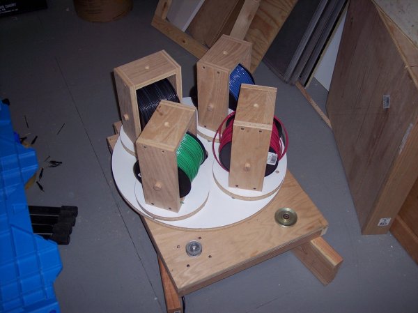
If you take 10 feet of two or three wires, and twist them while allowing the far ends to be free, you will not introduce twist of the individual conductors. The bundle will remain tighter as a result. If you make a twisting fixture that held the feed spools, and forced the spools to not rotate relative to you, yet revolve around each other, that will work. If you make the spools rotate in the opposite direction of the revolving, you can pre-load the conductors such that they will try to twist the bundle more and remain in good contact. I made one using a 12 inch lazy susan, 4 6 inchers, some plywood, and 4 spools of #12awg from HD. I'll attach a pic when I find it..

Also, I believe you would need to be concerned with not only the impedance between + and pin 1, - and pin 1, bit also between + and -. Could a triad even be done that would accomplish that? Maybe an over/under braiding, but I'm not sure that would net out to the same thing.

--Bill
Twisting will work to accomplish controlled impedance of all combinations. It is only important that the cross sectional geometry remain the same. As I pointed out, a tri twist does not give common centroids for any combination of two, but only for all three, so will by design, make the cable a tad more susceptible to nearfield time varying flux fields.

Cheers, jn

ps...apologize for the size of the picture, I'm still learning here...
 

Attachments

  • 100_1305..jpg
    100_1305..jpg
    473.2 KB · Views: 146

bblue

Well-Known Member
Apr 26, 2011
360
3
388
San Diego, CA
Very interesting. Thanks for the explanation. I never gave the untwist issue much thought.

On the pix, all you needed to to is size it down to something like 800x600 or whatever the recommended size is for WBF. Looks good, though!

--Bill
 

NorthStar

Member
Feb 8, 2011
24,305
1,323
435
Vancouver Island, B.C. Canada
Yeah, that picture is for sure very large!

* I wish I could help you out on how to resize it smaller, but I just don't know.
Perhaps another gentle member could. :b
 

Johnny Vinyl

Member Sponsor & WBF Founding Member
May 16, 2010
8,570
51
38
Calgary, AB
Easy.....open up MS Paint and reduce your picture using the % option. Use the Save As option so you still retain the orginal and now have a smaller duplicate.
 

j_n

New Member
Nov 18, 2011
39
0
0
Yeah, that picture is for sure very large!
Ah, I just figured out why...that's my 535 kcmil twisting fixture. The plywood is 7 inches thick, the sheetrock screws are 12 inches long with three inch heads...and the motor is a 3 phase 200 hp beast..

I'll be sure to reduce the naked jpegs on my hard drive prior to uploading again..sorry bout that.

Cheers, jn
 

NorthStar

Member
Feb 8, 2011
24,305
1,323
435
Vancouver Island, B.C. Canada
Ah, I just figured out why...that's my 535 kcmil twisting fixture. The plywood is 7 inches thick, the sheetrock screws are 12 inches long with three inch heads...and the motor is a 3 phase 200 hp beast..

I'll be sure to reduce the naked jpegs on my hard drive prior to uploading again..sorry bout that.

Cheers, jn

If you could resize that one above, just like John explained to you, that would be real swell. :b

Cheers,
Bob
 

HiroPro

New Member
Feb 14, 2012
2
0
0
There seems to be some confusion or misunderstanding of balanced inputs and outputs.

A true balanced input (pins 2 and 3 of an xlr) rejects anything in common to those signal lines based on impedance matching, which must be carefully controlled in the cabling to be effective. In a balanced input the two signal lines do NOT have to be differential. In fact, only one of them has to contain audio if you don't want the 6db gain provided by differential signals. As long as those two signal lines are driven by an equal impedance and the cabling maintains a consistent impedance throughout its run, the balanced input will reject any signal that is in common to them, such as EMI, RF, clicks and pops, or whatever. Even the capacity of the signal lines can become moot in this scheme.

But a differential signal may not necessarily be impedance matched, or maintained along the IC run, and therefore does not have the advantage of common mode rejection at the input. Also, differential inputs may not necessarily be balanced.

Of possibly greater significance is the IC itself. A traditional balanced IC is a twisted pair inside a tight shield, as this is the easiest way to maintain a constant impedance from end to end. A so-called balanced IC that is unshielded and simply connects pin 1 to pin 1, pin 2 to pin 2 and pin 3 to pin 3 on the XLR ends, is NOT balanced. This is a worst case IC because not only is it not shielded (or is shielded in total, not just signal pins 2 and 3) its signal runs (pins 2 and 3) are not impedance maintained. Therefore at the balanced input its performance is anybodies guess. An unshielded IC with pins 2 and 3 wiring carefully impedance matched end to end MAY have pretty decent characteristics at a balanced input.

So there's a lot to consider when you argue about the merits (or not) of 'balanced' wiring.

My own take is that in all cases except simple short runs (some exceptions), true balanced differential wiring is preferred for accuracy and consistency of the signal. It also treats the + and - signal lines equally.

To me, unbalanced in general is flawed when connecting different chassis and internal chassis wiring topologies together because it treats the signal lines differently. The unbalanced 'hot' pin may be some exotic wire construction, but the other side of the signal (the return) is carried by a shield, a ground wire, or what have you, of a completely different topology. Some cables (MIT, Monster, several others) use the same conductor type for both signal lines of an unbalanced cable, and utilize a telescoping shield originating from the source but not connected at the target. That's an improvement. But in a system where there are many chassis interconnected, there can be multiple (and often different types of wire) connections which make subtle contributions to the return path (only) of all involved IC paths. I hope I'm explaining this in an understandable manner. It's a complicated issue and not easily resolved unless a system wide approach is made, which takes into account the internal grounding topologies of each piece of equipment, and how each piece is connected to power. (When using grounding power cables, there is yet another return path which becomes an influence on the audio return path). Proper balanced interconnects eliminates all of this.

--Bill

Great post that explains it well. Also if anyone is interested Rane has some nice whitepapers on the topic.

http://www.rane.com/note110.html

http://www.rane.com/note165.html

If you guys are looking for a GREAT BALANCED IC then I suggest Mogami W3173 cable. It's meant for use with AES/EBU but it works fantastic for analog.

http://www.mogamicable.com/category/bulk/dig_interface/aes_ebu/

A company called Redco can make custom assemblies using that cable.

Redco is the Bluejeans of pro audio. FANTASTIC OUTFIT for ICs/assemblies !!!

http://www.redco.com/shopdisplayproducts.asp?id=126&cat=Design+Your+Own+Custom+Cable

BTW any IC that cost more than $200 is simply a SCAM.
 

About us

  • What’s Best Forum is THE forum for high end audio, product reviews, advice and sharing experiences on the best of everything else. This is THE place where audiophiles and audio companies discuss vintage, contemporary and new audio products, music servers, music streamers, computer audio, digital-to-analog converters, turntables, phono stages, cartridges, reel-to-reel tape machines, speakers, headphones and tube and solid-state amplification. Founded in 2010 What’s Best Forum invites intelligent and courteous people of all interests and backgrounds to describe and discuss the best of everything. From beginners to life-long hobbyists to industry professionals, we enjoy learning about new things and meeting new people, and participating in spirited debates.

Quick Navigation

User Menu

Steve Williams
Site Founder | Site Owner | Administrator
Ron Resnick
Site Co-Owner | Administrator
Julian (The Fixer)
Website Build | Marketing Managersing