Cable Modems
- Thread starter Xymox
- Start date
You are using an out of date browser. It may not display this or other websites correctly.
You should upgrade or use an alternative browser.
You should upgrade or use an alternative browser.
Does it makes sense from a SQ POV to disable all WiFi 6 functionality and let a device operate in WiFi 5 mode only?WiFi 6 introduces a lot of jitter because of the way it works.
Thx
Matt
why not try it? provided there is a setting for it trying should be easy enoughDoes it makes sense from a SQ POV to disable all WiFi 6 functionality and let a device operate in WiFi 5 mode only?
Thx
Matt
@Xymox You are absolutely right about wifi 6 access points having more jitter.
I had to remove the non wifi 6 TP link access point because it was dropping connections.
I put the wifi 6 access point back in and it sounds terrible, even though it’s only used to control music playback. My streamer is not connected to it.
I’m going to try Aruba access point next.
Careful doing Aruba. Make SURE to get a IAP-xxx not a AP-xxx... The AP-xxx only work with a expensive controller. The IAPs are "instant and have a wifi interface. They do take more work and some experence doing them. Ebay is a great source for them. You can feed them from a linear 12V.
ALSO make sure to get a US one.. While the RW ( rest of world ) ones DO work, they are illegal in the US. They can work on freq and powers that are illegal in the US. So look for IAP-xxx-US
You can still hit 850Mbps on wifi 5. So IMHO, no one really NEEDS wifi 6. Now wifi 6E, that has some things other then speed. BUT for audio use, just to control roon or a Taiko or something, wifi 5 on 5Ghz ( to get it up away from interferring ) turning off 2.4 and maybe more adjustments would seem like a great way to go.Does it makes sense from a SQ POV to disable all WiFi 6 functionality and let a device operate in WiFi 5 mode only?
Thx
Matt
Yea I used multiping set to 50 pings a second and recorded a chart pinging off a ipad thru some wifi systems. Wifi 6 always introduced more jitter ( like the measurable IT kind ) VS wifi 5. There was a near doubling of jitter. Latency also increased. WHich makes sense sorta as the wifi controller had to do more work to handle the wifi 6..
It could be that it was different Wifi chips, different mfgrs.. I have not jumped that deep into wifi devcies as the audio does not pass thru them, so, I have not cared too much..
I have not ever cracked open a Aruba. I think I might tho.
You can still hit 850Mbps on wifi 5. So IMHO, no one really NEEDS wifi 6. Now wifi 6E, that has some things other then speed. BUT for audio use, just to control roon or a Taiko or something, wifi 5 on 5Ghz ( to get it up away from interferring ) turning off 2.4 and maybe more adjustments would seem like a great way to go.
Yea I used multiping set to 50 pings a second and recorded a chart pinging off a ipad thru some wifi systems. Wifi 6 always introduced more jitter ( like the measurable IT kind ) VS wifi 5. There was a near doubling of jitter. Latency also increased. WHich makes sense sorta as the wifi controller had to do more work to handle the wifi 6..
It could be that it was different Wifi chips, different mfgrs.. I have not jumped that deep into wifi devcies as the audio does not pass thru them, so, I have not cared too much..
I have not ever cracked open a Aruba. I think I might tho.
I have used this aruba for wifi 5. You get a lot of settings and control. It does require some work and study to use them tho.
I am not saying these are best for audio use, but, they might be. Turned way down in power and then set for a specific band and further tuned in other RF ways like capped at lower speed connections.. These can be fed from a 12V 2A linear.
They are dirt cheap. https://www.ebay.com/itm/185373849608?epid=15013525942&hash=item2b29247808:g:5rsAAOSw-NZiTJ1r
Just a quick start.. You plug them in, you must also plug into ethrnet port 0 into your network. Then with a laptop wait for them to appear in the wifi list as a new Instant listing. Connect to it and then login is admin and the serial #. Start by adding ( + ) a new "network" which is your wifi. Follow prompts. You will setup your SSID ( wifi name ) and password and stuff. Leave defaults. Save and your done initially.
I changed some wifi settings on my non wifi 6 TP Link TL-WA901N.
Hopefully it will be reliable now.
No question, it’s a night and day difference using this access point versus a TP Link wifi 6 access point.
It is incredible how much a wifi 6 access point will degrade streaming music, just by being plugged into the router.
I’m sure there are unaware audiophiles with SOTA streaming setups who are spending thousands on network optimizations while using a wifi 6 access point.
@Xymox thank you for this discovery.
I am just curious, did you compare it to the Mikrotik mAP lite?TP Link TL-WA901N
Thx
Matt
Last edited:
I was doing some measurements of before and after the tweaks I do to the switch X today.
This is VERY typical for what i do do devices. The below spectrum analysis are on the 0.98V power supply that feeds the CPU/Switch chip on my Switch X. This power supply is created with a PWM switching regulator. Basically every piece of digital electronics around you has at least 3 of these feeding various chips. THESE ARE CRITICAL to the operation of the chip and device. Noise on these supplies ends up on all your signals and this noise also ends up as phase noise on clocks and even jitter on busses and digital signals. This noise is bad stuff and its in everything. Noise on power supply rails to chips results in noise on the signals and phase noise on the clocks.
I have been dealing with it for many years. The AppleTV X is a good example. The results of eliminating this BS seriously improves many aspects of device performance in many ways.
The RF these PWM regulators spew all over gets into everything and pollutes everything on the board and it even gets out of the devices and pollutes other devices by transmitting thru the air to other cables and devices.
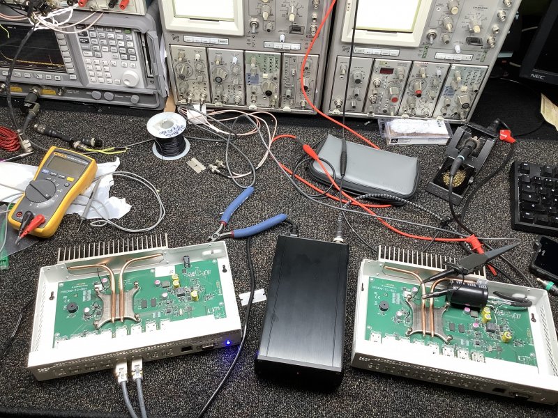
So my setup to do these ABs. I just moved between the 2 units with a probe.
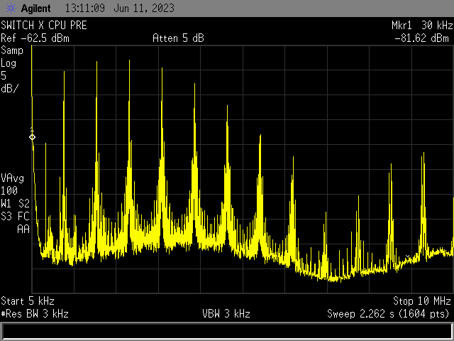
This is 5khz to 10Mhz. This is the 0.98V supply that feeds the CPU. Its the most polluting as jitter and radiated noise go everywhere.
All of these before and after mods are just normal for what I do.
This is the mess that comes from a PWM regulator. This is on the regulated "DC" voltage that feeds the CPU. This nasty BS causes all manner of jitter and you can pick up this spectrum of RF noise in the air 6 inches away from the regulator and on the ethernet signals. Its harmonic based on the fundamental freq of the clock for the PWM regulator, in this case 766Khz and it splatters all the way up to and past 10Mhz.
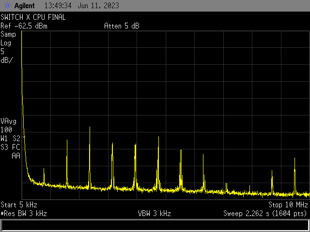
This is what it looks like once I am done. Same scale.. I can't get rid of it completly, but its reduced so much this is nearly negligible.
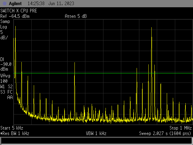
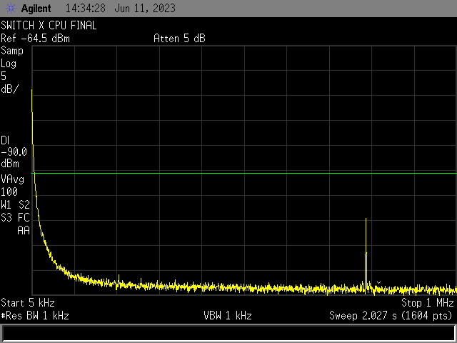
Zooming in much closer to the critical 5khz to 1Mhz spectrum.. You can clearly see the 766 khz primary clock feeding the PWM regulator as the peak and group of harmonics towards the right. You can also see all the harmonics related to it. ALL of this could jitter the CPU or the RF noise radiated thru things could cause noise and jitter in other sections of the device..
This is nasty stuff and has harmonics down lower then 5Khz RF. Very penetrating RF BS.
The final result of the mods on this critical band..
The primary PWM clock and a few harmonics are barely visible staying at the same scale. Its all still there, just radically reduced in level.
I can do this same thing to most any device and its always dramatic results. The AppleTV X was shocking. My new Switch X will be interesting..
I think I am going to tackle a Intel NUC soon. These little computers that can run Linux or windows and run a roon core or do NAS look like a worthy target. I don't think a big intense mother board and a insane set of CPUs is needed for audio work. In fact I think all that is a downside as dealing with all that comes at a expense. You really can't drop noise and jitter as much in big designs like a Taiko. I think smaller and way less power and complexity might be better.. We shall see..
I need to finish up some production runs of Switch Xs and ATVXs and then I will order up a NUC and jump into that.
This is VERY typical for what i do do devices. The below spectrum analysis are on the 0.98V power supply that feeds the CPU/Switch chip on my Switch X. This power supply is created with a PWM switching regulator. Basically every piece of digital electronics around you has at least 3 of these feeding various chips. THESE ARE CRITICAL to the operation of the chip and device. Noise on these supplies ends up on all your signals and this noise also ends up as phase noise on clocks and even jitter on busses and digital signals. This noise is bad stuff and its in everything. Noise on power supply rails to chips results in noise on the signals and phase noise on the clocks.
I have been dealing with it for many years. The AppleTV X is a good example. The results of eliminating this BS seriously improves many aspects of device performance in many ways.
The RF these PWM regulators spew all over gets into everything and pollutes everything on the board and it even gets out of the devices and pollutes other devices by transmitting thru the air to other cables and devices.
So my setup to do these ABs. I just moved between the 2 units with a probe.

This is 5khz to 10Mhz. This is the 0.98V supply that feeds the CPU. Its the most polluting as jitter and radiated noise go everywhere.
All of these before and after mods are just normal for what I do.
This is the mess that comes from a PWM regulator. This is on the regulated "DC" voltage that feeds the CPU. This nasty BS causes all manner of jitter and you can pick up this spectrum of RF noise in the air 6 inches away from the regulator and on the ethernet signals. Its harmonic based on the fundamental freq of the clock for the PWM regulator, in this case 766Khz and it splatters all the way up to and past 10Mhz.

This is what it looks like once I am done. Same scale.. I can't get rid of it completly, but its reduced so much this is nearly negligible.

Zooming in much closer to the critical 5khz to 1Mhz spectrum.. You can clearly see the 766 khz primary clock feeding the PWM regulator as the peak and group of harmonics towards the right. You can also see all the harmonics related to it. ALL of this could jitter the CPU or the RF noise radiated thru things could cause noise and jitter in other sections of the device..
This is nasty stuff and has harmonics down lower then 5Khz RF. Very penetrating RF BS.

The final result of the mods on this critical band..
The primary PWM clock and a few harmonics are barely visible staying at the same scale. Its all still there, just radically reduced in level.

I can do this same thing to most any device and its always dramatic results. The AppleTV X was shocking. My new Switch X will be interesting..
I think I am going to tackle a Intel NUC soon. These little computers that can run Linux or windows and run a roon core or do NAS look like a worthy target. I don't think a big intense mother board and a insane set of CPUs is needed for audio work. In fact I think all that is a downside as dealing with all that comes at a expense. You really can't drop noise and jitter as much in big designs like a Taiko. I think smaller and way less power and complexity might be better.. We shall see..
I need to finish up some production runs of Switch Xs and ATVXs and then I will order up a NUC and jump into that.
Would you consider adopting me as your cousin, Chris?!I was doing some measurements of before and after the tweaks I do to the switch X today.
This is VERY typical for what i do do devices. The below spectrum analysis are on the 0.98V power supply that feeds the CPU/Switch chip on my Switch X. This power supply is created with a PWM switching regulator. Basically every piece of digital electronics around you has at least 3 of these feeding various chips. THESE ARE CRITICAL to the operation of the chip and device. Noise on these supplies ends up on all your signals and this noise also ends up as phase noise on clocks and even jitter on busses and digital signals. This noise is bad stuff and its in everything. Noise on power supply rails to chips results in noise on the signals and phase noise on the clocks.
I have been dealing with it for many years. The AppleTV X is a good example. The results of eliminating this BS seriously improves many aspects of device performance in many ways.
The RF these PWM regulators spew all over gets into everything and pollutes everything on the board and it even gets out of the devices and pollutes other devices by transmitting thru the air to other cables and devices.
So my setup to do these ABs. I just moved between the 2 units with a probe.
View attachment 111731
This is 5khz to 10Mhz. This is the 0.98V supply that feeds the CPU. Its the most polluting as jitter and radiated noise go everywhere.
All of these before and after mods are just normal for what I do.
This is the mess that comes from a PWM regulator. This is on the regulated "DC" voltage that feeds the CPU. This nasty BS causes all manner of jitter and you can pick up this spectrum of RF noise in the air 6 inches away from the regulator and on the ethernet signals. Its harmonic based on the fundamental freq of the clock for the PWM regulator, in this case 766Khz and it splatters all the way up to and past 10Mhz.
View attachment 111732
This is what it looks like once I am done. Same scale.. I can't get rid of it completly, but its reduced so much this is nearly negligible.
View attachment 111733
Zooming in much closer to the critical 5khz to 1Mhz spectrum.. You can clearly see the 766 khz primary clock feeding the PWM regulator as the peak and group of harmonics towards the right. You can also see all the harmonics related to it. ALL of this could jitter the CPU or the RF noise radiated thru things could cause noise and jitter in other sections of the device..
This is nasty stuff and has harmonics down lower then 5Khz RF. Very penetrating RF BS.
View attachment 111734
The final result of the mods on this critical band..
The primary PWM clock and a few harmonics are barely visible staying at the same scale. Its all still there, just radically reduced in level.
View attachment 111735
I can do this same thing to most any device and its always dramatic results. The AppleTV X was shocking. My new Switch X will be interesting..
I think I am going to tackle a Intel NUC soon. These little computers that can run Linux or windows and run a roon core or do NAS look like a worthy target. I don't think a big intense mother board and a insane set of CPUs is needed for audio work. In fact I think all that is a downside as dealing with all that comes at a expense. You really can't drop noise and jitter as much in big designs like a Taiko. I think smaller and way less power and complexity might be better.. We shall see..
I need to finish up some production runs of Switch Xs and ATVXs and then I will order up a NUC and jump into that.
Over the weekend I changed some settings on my Technicolor WiFi 6 gateway with Broadcom chip.
The 2.4GHz operates now on WiFi 4, the 5GHz on WiFi 5.
I like the result, greater musicality, more fun to listen to music.
There is a small penalty, the internet speed is reduced by about 20%, that's all.
Thanks @Xymox and @vert
Matt
The 2.4GHz operates now on WiFi 4, the 5GHz on WiFi 5.
I like the result, greater musicality, more fun to listen to music.
There is a small penalty, the internet speed is reduced by about 20%, that's all.
Thanks @Xymox and @vert
Matt
Last edited:
XymoxI was doing some measurements of before and after the tweaks I do to the switch X today.
This is VERY typical for what i do do devices. The below spectrum analysis are on the 0.98V power supply that feeds the CPU/Switch chip on my Switch X. This power supply is created with a PWM switching regulator. Basically every piece of digital electronics around you has at least 3 of these feeding various chips. THESE ARE CRITICAL to the operation of the chip and device. Noise on these supplies ends up on all your signals and this noise also ends up as phase noise on clocks and even jitter on busses and digital signals. This noise is bad stuff and its in everything. Noise on power supply rails to chips results in noise on the signals and phase noise on the clocks.
I have been dealing with it for many years. The AppleTV X is a good example. The results of eliminating this BS seriously improves many aspects of device performance in many ways.
The RF these PWM regulators spew all over gets into everything and pollutes everything on the board and it even gets out of the devices and pollutes other devices by transmitting thru the air to other cables and devices.
So my setup to do these ABs. I just moved between the 2 units with a probe.
View attachment 111731
This is 5khz to 10Mhz. This is the 0.98V supply that feeds the CPU. Its the most polluting as jitter and radiated noise go everywhere.
All of these before and after mods are just normal for what I do.
This is the mess that comes from a PWM regulator. This is on the regulated "DC" voltage that feeds the CPU. This nasty BS causes all manner of jitter and you can pick up this spectrum of RF noise in the air 6 inches away from the regulator and on the ethernet signals. Its harmonic based on the fundamental freq of the clock for the PWM regulator, in this case 766Khz and it splatters all the way up to and past 10Mhz.
View attachment 111732
This is what it looks like once I am done. Same scale.. I can't get rid of it completly, but its reduced so much this is nearly negligible.
View attachment 111733
Zooming in much closer to the critical 5khz to 1Mhz spectrum.. You can clearly see the 766 khz primary clock feeding the PWM regulator as the peak and group of harmonics towards the right. You can also see all the harmonics related to it. ALL of this could jitter the CPU or the RF noise radiated thru things could cause noise and jitter in other sections of the device..
This is nasty stuff and has harmonics down lower then 5Khz RF. Very penetrating RF BS.
View attachment 111734
The final result of the mods on this critical band..
The primary PWM clock and a few harmonics are barely visible staying at the same scale. Its all still there, just radically reduced in level.
View attachment 111735
I can do this same thing to most any device and its always dramatic results. The AppleTV X was shocking. My new Switch X will be interesting..
I think I am going to tackle a Intel NUC soon. These little computers that can run Linux or windows and run a roon core or do NAS look like a worthy target. I don't think a big intense mother board and a insane set of CPUs is needed for audio work. In fact I think all that is a downside as dealing with all that comes at a expense. You really can't drop noise and jitter as much in big designs like a Taiko. I think smaller and way less power and complexity might be better.. We shall see..
I need to finish up some production runs of Switch Xs and ATVXs and then I will order up a NUC and jump into that.
I love reading about your efforts but I have 2 questions (that I'm sort of embarrassed to ask). I obviously don''t know the extent of the noise reduction modifications that you have performed but based on what I see, it appears that there is an obvious addition of a large capacitor on the board that presumably contributes to the improved filtered noise performance you have shown so nicely between 5K and 10K. So my questions are:
1) If the improvements gained are so impressive from what appears to be a minimal additional of hardware, one has to wonder why the manufacturer doesn't employ these modest modifications themselves? Is it engineering competence? Cost? Other?
2) The bigger question is on the issue of presumed SQ improvement. We have seen/read many reports of seasoned users who have made great efforts (often at considerable expense) to use devices that provide "clean" power, but report their disappointment that the resultant sound was either unimproved or in some cases actually worse than using no power conditioning at all. Could the failure of some of these switch manufacturers not to employ what appears to be rather straight forward modifications such as you have performed be due to that fact they don't think that they really improve SQ after all is said and done?
Marty
I suspect router manufacturers don't believe routers can affect sound quality.Xymox
I love reading about your efforts but I have 2 questions (that I'm sort of embarrassed to ask). I obviously don''t know the extent of the noise reduction modifications that you have performed but based on what I see, it appears that there is an obvious addition of a large capacitor on the board that presumably contributes to the improved filtered noise performance you have shown so nicely between 5K and 10K. So my questions are:
1) If the improvements gained are so impressive from what appears to be a minimal additional of hardware, one has to wonder why the manufacturer doesn't employ these modest modifications themselves? Is it engineering competence? Cost? Other?
2) The bigger question is on the issue of presumed SQ improvement. We have seen/read many reports of seasoned users who have made great efforts (often at considerable expense) to use devices that provide "clean" power, but report their disappointment that the resultant sound was either unimproved or in some cases actually worse than using no power conditioning at all. Could the failure of some of these switch manufacturers not to employ what appears to be rather straight forward modifications such as you have performed be due to that fact they don't think that they really improve SQ after all is said and done?
Marty
Careful doing Aruba. Make SURE to get a IAP-xxx not a AP-xxx... The AP-xxx only work with a expensive controller. The IAPs are "instant and have a wifi interface. They do take more work and some experence doing them. Ebay is a great source for them. You can feed them from a linear 12V.
I tried Aruba AP-11, and it does work without a controller.
But I couldn’t get the WiFi working when the unit was powered by my linear power supply.
I assume your LPS is the same voltage as the stock supply? That is critical, but you also need sufficient current capability. Normally it is recommended to use a linear supply that is rated 15% higher than the SMPS it replaces.I tried Aruba AP-11, and it does work without a controller.
But I couldn’t get the WiFi working when the unit was powered by my linear power supply.
Some inexpensive supplies can't actually deliver what they claim. For example I bought a 12V LPS from eBay that claimed to be 50W for my router, but when I asked the supplier about the current rating, it was only 2A, which means it was actually only a 24W supply, insufficient for the router.
I assume your LPS is the same voltage as the stock supply? That is critical, but you also need sufficient current capability. Normally it is recommended to use a linear supply that is rated 15% higher than the SMPS it replaces.
Yes, I set the Uptone JS-2 to 12v. JS-2 is capable of 7.4 amps continuous at 12v, so that should be plenty of power. Aruba AP-11 only consumes 10w.
Would you consider adopting me as your cousin, Chris?!
Ooooo.... Can you solder ?
Similar threads
- Replies
- 5
- Views
- 329
- Replies
- 89
- Views
- 8K
- Replies
- 6
- Views
- 3K
- Replies
- 65
- Views
- 13K
| Steve Williams Site Founder | Site Owner | Administrator | Ron Resnick Site Owner | Administrator | Julian (The Fixer) Website Build | Marketing Managersing |


