Strange soft-clipping artifact

dtbradio

New Member
Jun 11, 2023
16
5
3
54
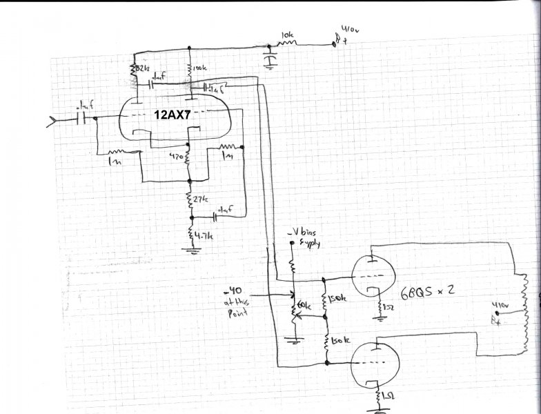
I encountered an odd-ball this morning. I'm working on my first attempt at a tube bass amp using the tubes and iron from a Baldwin 46C organ amp chassis. The power amp is a quad of 6BQ5's. I have the power section cathode-biased at roughly 65% for safety, and the PI is a JCM800 circuit but using a 12AU7 tube and a 27K tail instead of 10K. Coupling caps are all .1uf since this is for a bass. The 6BQ5 screen sets are fed through a pair of 10K resistors from the choke side of the power supply with 4.7uf screen decoupling to the preamp ground. The cathode resistors on each pair of 6BQ5's are a 1-ohm 1% resistor (for plate current measurement) in series with a 470 ohm 5% sand-block resistor. Grids have 150K to main chassis ground.

What I'm seeing is a bit of what looks like soft clipping at the outputs of the PI and the PA when the input goes past a certain point. This by itself is normal, since all amps clip at some point when the input increases. What is strange is that the clipping disappears if I put my hand near the output jack of the signal generator. I've attached extra grounds from the scope chassis to the amp chassis, and the signal generator is chassis-grounded via the output cable. I didn't notice the clipping change at all with my hand near any other cable or near the amp chassis itself (don't worry, I always observe safety precautions when working with high voltage). I have never seen this phenomenon with any other amp build.

My assumption is that somehow the 'scope measurement is somehow corrupt, since I don't see how my hand being near the jack (NOT touching, just near) would eliminate the clipping. Oh, the clipping isn't eliminated with the measured signal being reduced at all; instead, its as though the clipped off part is added back on to the sine wave tip.

Does anyone have any clue as to what I'm seeing here?
 

dtbradio

New Member
Jun 11, 2023
16
5
3
54
Well when you inject with a signal generator, you should use an isolation cap. A .01 in series with the positive lead would work. Otherwise, its going to effect the bias since its a dc coupled circuit

Thank you for your reply! The input cap on the PI blocks DC, making it an AC-coupled circuit. No additional cap needed or desired, as that would affect frequency response.
 
Last edited:

sparkie

Member
Dec 7, 2023
77
17
10
Rapid City, South Dakota
Thank you for your reply! The input cap on the PI blocks DC, making it an AC-coupled circuit. No additional cap needed or desired, as that would affect frequency response.
It makes no difference. If the coupling cap in the signal source is too big, it can load it down. This is a typical thing to do when testing and making adjustments to negative feedback. With tube amps , the two common sizes to use with signal injection is .1 or .01 cap.

You are making this for a bass guitar, correct?

If you are trying to use this with a PI permanently, you have to find the right size grid stop resistor.
take a 500K pot, use it as a adjustable resistor in the input grid circuit, and adjust it till it goes away. Its better to lift the negative feedback out of the circuit when doing this so you can work out all the hums and buzzes before attaching the negative feedback.
 
Last edited:

dtbradio

New Member
Jun 11, 2023
16
5
3
54
It makes no difference. If the coupling cap in the signal source is too big, it can load it down. This is a typical thing to do when testing and making adjustments to negative feedback. With tube amps , the two common sizes to use with signal injection is .1 or .01 cap.

You are making this for a bass guitar, correct?

If you are trying to use this with a PI permanently, you have to find the right size grid stop.

So another .1 (or .01) in series with the existing .1 PI input cap? Strange that I've never encountered injector coupling problems with any of my other amp builds, unless they were there and just not recognized. Yes, it is for a bass amp. Are you referring to grid stop in the PA or PI?

After some more testing, I'm beginning to suspect that my OPT may have failed. I see no AC amplification on the power tube plates (in fact almost no AC at all except for what looks like distorted low-voltage square waves, similar to what I encounter in AM communications radios that use transformer modulation and have blown transformers). About to test that theory now.
 

sparkie

Member
Dec 7, 2023
77
17
10
Rapid City, South Dakota
the cathode resistors on each pair of 6BQ5's are a 1-ohm 1% resistor (for plate current measurement) in series with a 470 ohm 5% sand-block resistor. Grids have 150K to main chassis ground.
that would be ok for fixed bias, but not self bias.
Remove the 470 ohm in the cathode, and increase the grid to ground resistor to 470K
That is why the output signal isn't looking like it should.
 

dtbradio

New Member
Jun 11, 2023
16
5
3
54
Yup, OPT shorted out. No idea how or why, but luckily I have two more from the same organ amp chassis. They are only 24 watters, though, so going to have to go with just a pair of the BQ's. Darn...
 

sparkie

Member
Dec 7, 2023
77
17
10
Rapid City, South Dakota
Grids have 150K to main chassis ground.
You should try the standard self bias resistor of 470K before throwing away the transformer. 150K your are not really self biasing the tube.

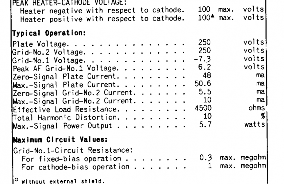
Edit: lets see, the datasheet says for class A is .3M max for that resistor (300K) and the typical affair is 470K in guitar amps.
Screenshot_2023-12-13_08-31-42.png
 
Last edited:

dtbradio

New Member
Jun 11, 2023
16
5
3
54
You should try the standard self bias resistor of 470K before throwing away the transformer. 150K your are not really self biasing the tube

Confirmed shorted transformer, tested out of the circuit. Will take it apart if I get time to find the actual short and maybe even attempt a rewind for the learning experience.

Good point on the different biasing needing different grid leaks, totally was overlooking that. I went back to fixed bias since I seem to now have a stable bias control POT. The cathode resistors = 1 ohm now for plate current measurements.

Working on installing the 24-watt transformer now, will see what I get after that's wired in.
 
  • Like
Reactions: sparkie

DasguteOhr

Well-Known Member
Sep 26, 2013
2,444
2,623
645
Germany
Do you have a circuit diagram of this amplifier or a sketch? Otherwise it's just poking around in the fog.
Exsample a 0.1 uf coupling cap with a 470 k gridleak resistor in front of the el 84 grid ensures a very low cutoff frequency response - 3 dB at 3.3 Hz. This extends the discharge time of the coupling capacitor. This can be seen very clearly if you measure the square wave at the speaker terminals. This puts a lot of strain on your output transformers. Unless this point is determined higher by the tube amp's input stage.
If you want a good fast amplifier please post the built circuit. so that you have a lot of fun listening to music
 

sparkie

Member
Dec 7, 2023
77
17
10
Rapid City, South Dakota
Do you have a circuit diagram of this amplifier or a sketch? Otherwise it's just poking around in the fog.
That is what confused me in the beginning.
Looks like he will go to a fixed bias.
But yes, the normal coupling is usually around .033 with that tube. I would try .01 to give it a tighter controlled sound.

The real question is, if he will need to increase the grid resistors from 150K to get more drive signal
 

DasguteOhr

Well-Known Member
Sep 26, 2013
2,444
2,623
645
Germany
That is what confused me in the beginning.
Looks like he will go to a fixed bias.
But yes, the normal coupling is usually around .033 with that tube. I would try .01 to give it a tighter controlled sound.

The real question is, if he will need to increase the grid resistors from 150K to get more drive signal
I keep the grid resistor as small as possible so that if the tube goes through, everything won't break and it brings stability in the amp too.
Exactly. I think it makes sense to keep the cutoff frequency in the range 10Hz-15Hz - 3dB. good impulse behavior and music is reproduced in full.
We will be able to do a diagnosis when we see the circuit.
P.S
Of course, it depends largely on the driver stage
 
Last edited:

sparkie

Member
Dec 7, 2023
77
17
10
Rapid City, South Dakota
I keep the grid resistor as small as possible so that if the tube goes through, everything won't break and it brings stability in the amp too.
Its a bias feed resistor. But for grid stops, you have to select a good resistor construction type to avoid insertion loss. I've made circuits with grid stops from 100K to 2M before and had no complaints. Its what they hear that counts.

Edit: But I use the formulas for the grid stop. As well as dc coupling resistors (if used). The popular small signal triodes are usually around 10K, Power triodes around 330 ohms and Pentodes are usually around 120K for grid stops
 
Last edited:

DasguteOhr

Well-Known Member
Sep 26, 2013
2,444
2,623
645
Germany
The OPT is terminated with a 15-ohm resistor.


View attachment 121689
Workingpoint 300 -310 Anode voltage , outtransformer 8-10 kohm primary winding (bias voltage ug- 16-18volt) or 270ohm kathode each el84. Or common cathode resistance 135ohm bypass cap 100uf for both. Output clean 8 watt.
Google grundig nf 20 amp great sounding amp
 
Last edited:

dtbradio

New Member
Jun 11, 2023
16
5
3
54
Again, thanks for all of the input! The OPT, tubes, PT, etc were all part of the power amp section from a Baldwin 46C organ. It had a 4-tube amplifier driving a 15" Jensen bass speaker, plus a pair of 2-tube amps driving a pair of 12" Jensen full-rangers. The only difference is I'm using solid state rectification instead of tube as the 5U4's tested bad. I can always try to find a couple 5U4's that won't break a Christmas budget, lol! I will check out that Grundig amp. I know I mentioned it in an earlier post, but this is intended for use with a Bass guitar in case that had been overlooked.
 
  • Like
Reactions: sparkie

About us

  • What’s Best Forum is THE forum for high end audio, product reviews, advice and sharing experiences on the best of everything else. This is THE place where audiophiles and audio companies discuss vintage, contemporary and new audio products, music servers, music streamers, computer audio, digital-to-analog converters, turntables, phono stages, cartridges, reel-to-reel tape machines, speakers, headphones and tube and solid-state amplification. Founded in 2010 What’s Best Forum invites intelligent and courteous people of all interests and backgrounds to describe and discuss the best of everything. From beginners to life-long hobbyists to industry professionals, we enjoy learning about new things and meeting new people, and participating in spirited debates.

Quick Navigation

User Menu

Steve Williams
Site Founder | Site Owner | Administrator
Ron Resnick
Site Co-Owner | Administrator
Julian (The Fixer)
Website Build | Marketing Managersing