Hi All,
I just completed an extensive project to revamp the delivery of electrical power to my listening room. Considering that the majority of expense was labor cost, I wasn’t terribly concerned about the cost of materials. Meaning, I spec’d the largest gauge wire that could be twisted tightly and pulled by a team of electricians (between MDP and sub panel) as well as the largest gauge branch circuit wire that could be terminated in my Furutech GTX Rodium NFC listening room duplexes. My approach was heavily influenced by the advice of Vince Galbo from MSB (and his whitepaper), Rex Hungerford and Art Kelm.
Before describing the details of my project, I’ll say that the outcome was SPECTACULAR. The sonic improvement yielded was far more significant than any component upgrade I could have envisioned at any price. Considering what I spent to implement it (5-7 electricians per day for a week + material cost), I took a pretty big risk. There was no ability to audition this “component” before purchase. That being said, my system is now operating at a level that FAR EXCEEDED my expectations (no placebo here or sense that it may sound a little better but not quite sure…IT’S A NIGHT AND DAY DIFFERENCE). And the crazy thing is that it far outperforms my system prior to the power upgrade where my digital front end was an MSB Select, that I sold a couple weeks ago, in anticipation of my MSB Cascade which arrives on Monday. In the meantime, I’m using an old Meridian 818v3 DAC that’s been gathering dust in a closet. Still, even with this 10+ year old DAC, the system is performing better IMHO, than any system I’ve heard in a dealer’s listening room, at shows, etc. Now my sample set may be limited, and I understand that there are certainly many systems that outperform mine, but the reason I mention this is that for those of you who haven’t taken a no holds barred approach to upgrading your power delivery, doing so may be the single most economical and significant upgrade you can make to your system. Otherwise, without optimizing your power delivery, you may be wasting $s on high end equipment / upgrades or driving your sports car in first gear for years without even touching its potential. After only listening to my system for a couple hours post power upgrade (from a cold state), the dynamic range and weight and density of the artists and instruments are off the charts, the spatial cues are effortlessly communicated through the track–when an artist mumbles or whispers to a bandmate during a session, it sounds like you are part of the conversation–vocals have significant density and extend all the way to the listening position, the rhythm and pace of the music just sound “right”. As I listen, layers of music wash over me, and I no longer critique my system, or listen to the better part of a track before jumping to the next song. My system just grew a gigantic set of low hanging BALLS….I’m posting my experience for the benefit of others who are “pretty” happy with their systems, enjoy a component upgrade for a few weeks before chasing the next one, or love their system one day but not the next. That was me for many years.
This was the scope and details of my project:
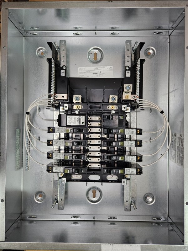
- from my 600A service entry MDP (Quad D I-Line w/ copper bus) I ran a 175’ 125A 120v 1/0-1/0-1/0 + 8 AWG ground circuit (hot and neutral were twisted tightly at 2-2.5 twists per foot; ground wire was not twisted and left loose in the PVC conduit; the spare 1/0 was not twisted and will serve as a neutral in the event I run 240v in the future) to a sub panel that feeds five 35’ 120v 20A branch circuits (3-4 twists per foot) to listening room duplexes. I am fortunate in that I have dedicated pole/transformer that I do not share with my neighbors. Also, per Rex’s recommendation the 125A breaker feeding the 1/0 circuit, it was seated in the slot closest to the incoming 600A utility service.
- also worth mentioning that prior to choosing which A/C phase to seat the 125A breaker in the MDP, we used a Greenwave noise meter to test the broadband noise on each incoming phase, and chose the quietest (1300mv). We did not consider moving “noisy” appliances in the 5 sub panels that the MDP also powers, since all appliances, etc. share the same neutral in the MDP. And, that would have been huge undertaking. For what it is worth, the noise reading at my listening room duplexes are ~1200mv. That may be high but it is consistent with the noise level being delivered on the utility lines. Nothing I can do about that besides rely upon my listening room power conditioner to filter or consider an industrial sized isolation transformer before the sub panel in the future.
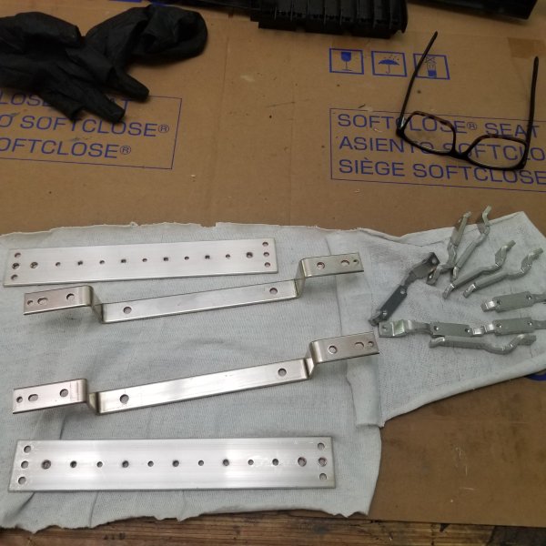
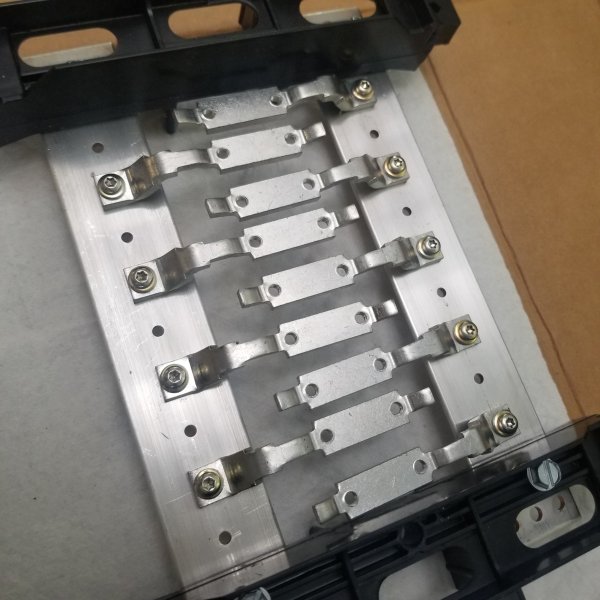
- regarding sub panel, I teetered between Eaton CH and Quad D’s QO line. I ultimately chose the former because it had a silver flashed bus bar vs. the latter which had a tin flashed bus bar. Silver is a better conductor but oxidizes more quickly. Not sure one is better from the other. I would have spec’d a sub panel custom built by Rex, but my time table did not allow that. Could be a potential upgrade in the future. Another option would have been a Quad D NQ panel but they require 20” stud bays of which I have “16. And I did not want to surface mount it.
- regarding the branch circuits, with some ingenuity, resolve and elbow grease, two were landed with twisted 6AWG romex into my GTX-D R NCF duplexes, while the other three were landed with 10 AWG cryo’d Romex. In all cases, the ground wire in the romex jacket was not used; instead, we ran a 10AWG solid core copper ground for each circuit. These grounds were not twisted and left loose in the conduit. All branch circuits lengths were cut to exactly the same lengths. I’ll report back on which gauge sounds better in my system. Know Rex prefers 10AWG, but based on a brief A/B, my MSB Amp may prefer the 6AWG. Attack appears to be more powerful and imaging denser when powered by the 6 AWG circuity, but it’s way too early for me to declare a victor.
- MSB S202 is plugged into the wall while my source components into a Shunyata 6000v2 power conditioner.
- expecting the live bus bars of my I-Line MDP, all connections, breakers, wire terminals and outlets were treated with Deoxit DN5-100 followed by Deoxit GN5-100
- We did not use silver paste. We had no junctions or pigtails in the circuits where it may have been useful. Would have been way too messy to use on the duplex connections, which were a beast to land with the 6AWG. Could have considered using it in the sub panel, but we were rushed at the end and the electricians’ were already at their ropes end.
- regarding outdoor grounding, the ground resistance at my MDP read less than 0.5 ohms, so while I considered adding supplemental ground rods, for now, I don’t believe I need them. My understanding that less than 0.5 ohms is very good.
- there are wire resistance calculators online that you can use to compute circuit resistance based upon length, current delivery, frequency, etc. depending on wire gauge and whether that is stranded, solid, copper, etc. I purposely spec’d wire gauge that would present the lowest resistance path between the MDP and listening room duplexes that could be twisted tightly with the ground wire left loose, was not so heavy or unwieldy that it could not be run over a long distance with the muscle of a team of electricians, and landed in duplexes without downsizing gauge via junction boxes and pigtails. Regarding the latter, the majority of the industry expertise I consulted recommend avoiding junctions and pigtails at all cost. Others may share a differing point of view, but I wanted to optimize continuity from MDP to duplexes.
- Finally, while it was recommended on several occasions, I did not implement an isolation transformer between the MDP and sub panel (or an isolation transformer sub panel), which I may consider in the future to address high frequency noise that is unavoidable given the length of my circuits and what noise is coming into my MDP from the utility service. However, my branch circuits are still reasonably long (35’), so if I were to consider an isolation transformer, I’d need to ensure whether the impedance that the isolation transformer introduced into he circuit wouldn’t limit current delivery to my components. Most experts recommend that an isolation transformer is not longer than 25’ from the duplexes. In my case, that is not feasible unless I were to implement a rack mounted model.
In sum, while YMMV depending on the variable nature of your system, utility service, ability to run dedicated circuits and the gauge thereof, I wanted to share my experience and the level of detail I applied to my project. Vince and his whitepaper were incredibly helpful in the development of my approach, while Rex and Art were very helpful in answering hardware specific questions as I formalized my plan. A big thanks to all!
Blake
Helpful Links:
Vince’s Whitepaper: https://drive.google.com/drive/mobile/?usp=docs_web&pli=1
Twisting Conductors to Mitigate Noise Whitepaper: https://www.jensen-transformers.com...est-of-Story-Whitlock-Fox-Generic-Version.pdf
I just completed an extensive project to revamp the delivery of electrical power to my listening room. Considering that the majority of expense was labor cost, I wasn’t terribly concerned about the cost of materials. Meaning, I spec’d the largest gauge wire that could be twisted tightly and pulled by a team of electricians (between MDP and sub panel) as well as the largest gauge branch circuit wire that could be terminated in my Furutech GTX Rodium NFC listening room duplexes. My approach was heavily influenced by the advice of Vince Galbo from MSB (and his whitepaper), Rex Hungerford and Art Kelm.
Before describing the details of my project, I’ll say that the outcome was SPECTACULAR. The sonic improvement yielded was far more significant than any component upgrade I could have envisioned at any price. Considering what I spent to implement it (5-7 electricians per day for a week + material cost), I took a pretty big risk. There was no ability to audition this “component” before purchase. That being said, my system is now operating at a level that FAR EXCEEDED my expectations (no placebo here or sense that it may sound a little better but not quite sure…IT’S A NIGHT AND DAY DIFFERENCE). And the crazy thing is that it far outperforms my system prior to the power upgrade where my digital front end was an MSB Select, that I sold a couple weeks ago, in anticipation of my MSB Cascade which arrives on Monday. In the meantime, I’m using an old Meridian 818v3 DAC that’s been gathering dust in a closet. Still, even with this 10+ year old DAC, the system is performing better IMHO, than any system I’ve heard in a dealer’s listening room, at shows, etc. Now my sample set may be limited, and I understand that there are certainly many systems that outperform mine, but the reason I mention this is that for those of you who haven’t taken a no holds barred approach to upgrading your power delivery, doing so may be the single most economical and significant upgrade you can make to your system. Otherwise, without optimizing your power delivery, you may be wasting $s on high end equipment / upgrades or driving your sports car in first gear for years without even touching its potential. After only listening to my system for a couple hours post power upgrade (from a cold state), the dynamic range and weight and density of the artists and instruments are off the charts, the spatial cues are effortlessly communicated through the track–when an artist mumbles or whispers to a bandmate during a session, it sounds like you are part of the conversation–vocals have significant density and extend all the way to the listening position, the rhythm and pace of the music just sound “right”. As I listen, layers of music wash over me, and I no longer critique my system, or listen to the better part of a track before jumping to the next song. My system just grew a gigantic set of low hanging BALLS….I’m posting my experience for the benefit of others who are “pretty” happy with their systems, enjoy a component upgrade for a few weeks before chasing the next one, or love their system one day but not the next. That was me for many years.
This was the scope and details of my project:
- from my 600A service entry MDP (Quad D I-Line w/ copper bus) I ran a 175’ 125A 120v 1/0-1/0-1/0 + 8 AWG ground circuit (hot and neutral were twisted tightly at 2-2.5 twists per foot; ground wire was not twisted and left loose in the PVC conduit; the spare 1/0 was not twisted and will serve as a neutral in the event I run 240v in the future) to a sub panel that feeds five 35’ 120v 20A branch circuits (3-4 twists per foot) to listening room duplexes. I am fortunate in that I have dedicated pole/transformer that I do not share with my neighbors. Also, per Rex’s recommendation the 125A breaker feeding the 1/0 circuit, it was seated in the slot closest to the incoming 600A utility service.
- also worth mentioning that prior to choosing which A/C phase to seat the 125A breaker in the MDP, we used a Greenwave noise meter to test the broadband noise on each incoming phase, and chose the quietest (1300mv). We did not consider moving “noisy” appliances in the 5 sub panels that the MDP also powers, since all appliances, etc. share the same neutral in the MDP. And, that would have been huge undertaking. For what it is worth, the noise reading at my listening room duplexes are ~1200mv. That may be high but it is consistent with the noise level being delivered on the utility lines. Nothing I can do about that besides rely upon my listening room power conditioner to filter or consider an industrial sized isolation transformer before the sub panel in the future.
- regarding sub panel, I teetered between Eaton CH and Quad D’s QO line. I ultimately chose the former because it had a silver flashed bus bar vs. the latter which had a tin flashed bus bar. Silver is a better conductor but oxidizes more quickly. Not sure one is better from the other. I would have spec’d a sub panel custom built by Rex, but my time table did not allow that. Could be a potential upgrade in the future. Another option would have been a Quad D NQ panel but they require 20” stud bays of which I have “16. And I did not want to surface mount it.
- regarding the branch circuits, with some ingenuity, resolve and elbow grease, two were landed with twisted 6AWG romex into my GTX-D R NCF duplexes, while the other three were landed with 10 AWG cryo’d Romex. In all cases, the ground wire in the romex jacket was not used; instead, we ran a 10AWG solid core copper ground for each circuit. These grounds were not twisted and left loose in the conduit. All branch circuits lengths were cut to exactly the same lengths. I’ll report back on which gauge sounds better in my system. Know Rex prefers 10AWG, but based on a brief A/B, my MSB Amp may prefer the 6AWG. Attack appears to be more powerful and imaging denser when powered by the 6 AWG circuity, but it’s way too early for me to declare a victor.
- MSB S202 is plugged into the wall while my source components into a Shunyata 6000v2 power conditioner.
- expecting the live bus bars of my I-Line MDP, all connections, breakers, wire terminals and outlets were treated with Deoxit DN5-100 followed by Deoxit GN5-100
- We did not use silver paste. We had no junctions or pigtails in the circuits where it may have been useful. Would have been way too messy to use on the duplex connections, which were a beast to land with the 6AWG. Could have considered using it in the sub panel, but we were rushed at the end and the electricians’ were already at their ropes end.
- regarding outdoor grounding, the ground resistance at my MDP read less than 0.5 ohms, so while I considered adding supplemental ground rods, for now, I don’t believe I need them. My understanding that less than 0.5 ohms is very good.
- there are wire resistance calculators online that you can use to compute circuit resistance based upon length, current delivery, frequency, etc. depending on wire gauge and whether that is stranded, solid, copper, etc. I purposely spec’d wire gauge that would present the lowest resistance path between the MDP and listening room duplexes that could be twisted tightly with the ground wire left loose, was not so heavy or unwieldy that it could not be run over a long distance with the muscle of a team of electricians, and landed in duplexes without downsizing gauge via junction boxes and pigtails. Regarding the latter, the majority of the industry expertise I consulted recommend avoiding junctions and pigtails at all cost. Others may share a differing point of view, but I wanted to optimize continuity from MDP to duplexes.
- Finally, while it was recommended on several occasions, I did not implement an isolation transformer between the MDP and sub panel (or an isolation transformer sub panel), which I may consider in the future to address high frequency noise that is unavoidable given the length of my circuits and what noise is coming into my MDP from the utility service. However, my branch circuits are still reasonably long (35’), so if I were to consider an isolation transformer, I’d need to ensure whether the impedance that the isolation transformer introduced into he circuit wouldn’t limit current delivery to my components. Most experts recommend that an isolation transformer is not longer than 25’ from the duplexes. In my case, that is not feasible unless I were to implement a rack mounted model.
In sum, while YMMV depending on the variable nature of your system, utility service, ability to run dedicated circuits and the gauge thereof, I wanted to share my experience and the level of detail I applied to my project. Vince and his whitepaper were incredibly helpful in the development of my approach, while Rex and Art were very helpful in answering hardware specific questions as I formalized my plan. A big thanks to all!
Blake
Helpful Links:
Vince’s Whitepaper: https://drive.google.com/drive/mobile/?usp=docs_web&pli=1
Twisting Conductors to Mitigate Noise Whitepaper: https://www.jensen-transformers.com...est-of-Story-Whitlock-Fox-Generic-Version.pdf
Last edited: