harmonics and single-ended versus balanced audio cables

I calculate my interconnect length in the listening room at 45 feet.

That's a long IC for unbalanced, if it can be avoided, I'd avoid it. For those lengths the output section of (I'm guessing) your preamp needs to be able to drive long cables, that might rule out some preamps. It would seem almost impossible for a shielded cable that long to not have fairly high capacitance, which will make the sound dull especially if the pre has a higher output impedance. Pro gear is generally designed to drive long cables but tube preamps without follower outputs just can't do it.
 
There are a few low capacitance interconnects , Tara labs has low single digit capacitance interconnects. It's worth a search given a 45' run to amps. The Io has a low output impedence, HiFi news measured 65 ohms rising to 365 ohms at 20 hz. Max output of 38 volts combined with the low output impedence will help.
 
Last edited:
Do the technical people agree that "balanced" signal interconnection alone properly describes, from a technical point of view, the cancelation of common-mode noise?

Balanced avoids common-mode noise rather than cancels it. Cancellation suggests addition of equal but opposite noise which in practice is quite difficult to achieve accurately hence is only to be used if rejecting the noise in the first place can't be done for some reason.

But the end result is the same - balanced is indeed a fix for common-mode noise.
 
Because you should really be using a good SET preamplifier anyways. ;)

Well yeah but seems rather overkill when the source is a phone :)

Also, good transformers are expensive.

Commercially available ones yeah but not expensive in the context of the kit which is routinely talked about on here. Just one example (and I dunno if it already has an input trafo) but a Wavac amp - would scarcely have its price needle moved at all if an input trafo were added. DIY transformers OTOH are absurdly cheap in parts, just expensive when time is taken into account.
 
It rises at LF, or did you mean 20 kHz?

Normal cables range up to about 30 pF/foot so a 50 foot cable would have around 1.5 nF of capacitance. Ignoring inductance, assuming a 100-ohm source (about what I have seen for most SS preamps), and ignoring the load (should be high-impedance) that's about 2 MHz bandwidth. It would still be about 200 kHz for a 1 k-ohm source that might be closer to a tube with a cathode follower. A tube preamp without a cathode follower, other output buffer, or transformer would be a bit unusual and have a very high impedance output IME. The usual problem with such a long run is noise coupling, not signal loss, though of course opinions (and cables, and components) vary. I agree with DaveC, that would be a candidate for balanced runs, but if you have no problems it's probably OK.

There are cables that have additional shield layers so you can better isolate the signal ground from external noise. I have also used standard XLR cables, using the two inner conductors for signal positive and ground return, and only attaching the shield at one end (I attach at the source end by convention).
 
That's a long IC for unbalanced, if it can be avoided, I'd avoid it. For those lengths the output section of (I'm guessing) your preamp needs to be able to drive long cables, that might rule out some preamps. It would seem almost impossible for a shielded cable that long to not have fairly high capacitance, which will make the sound dull especially if the pre has a higher output impedance. Pro gear is generally designed to drive long cables but tube preamps without follower outputs just can't do it.

I have measured ICs having from around 50 pf up to 1000 pf (yes, 1000 pF! ) capacitance per meter. In terms of capacitance, this means that some 1m ICs will have as much capacitance as another having 20 meters (66 feet). We usually only think in terms of frequency response, but in some cases the increase of distortion at high frequency due to the decrease of impedance versus increasing frequencies can not be ignored.

Unfortunately each case is a particular case, only extreme situations can be easily ruled out.
 
I'm looking at Tara labs phono cables. They state low capacitance. Really low. Example, the Air Evolution interconnect is specified at 4 pf/foot.

I'm considering the Zero LX phono. I'm not sure if a any other cable company has such low capacitance?
 
It's trivially easy to make low capacitance ic cables but the inductance is larger and geometry is compromised. No free lunch!
 
Hi Don,

http://www.aesthetix.net/docs/Aesthetix HiFiNews Review.pdf

Measurements section said rising to 370 ohm at 25 hz.

The full measurements accessible at the Paul Miller site http://www.milleraudioresearch.com/download2011/reports/aug11/aesthetix_io_eclipse_aux.htmlshow that impedance starts raising slowly at around 200 Hz - most probably due to capacitor coupling. Cable capacitance is only relevant at high frequencies, the important value for this question is the 65 ohm.
 
It rises at LF, or did you mean 20 kHz?

Normal cables range up to about 30 pF/foot so a 50 foot cable would have around 1.5 nF of capacitance. Ignoring inductance, assuming a 100-ohm source (about what I have seen for most SS preamps), and ignoring the load (should be high-impedance) that's about 2 MHz bandwidth. It would still be about 200 kHz for a 1 k-ohm source that might be closer to a tube with a cathode follower. A tube preamp without a cathode follower, other output buffer, or transformer would be a bit unusual and have a very high impedance output IME. The usual problem with such a long run is noise coupling, not signal loss, though of course opinions (and cables, and components) vary. I agree with DaveC, that would be a candidate for balanced runs, but if you have no problems it's probably OK.

There are cables that have additional shield layers so you can better isolate the signal ground from external noise. I have also used standard XLR cables, using the two inner conductors for signal positive and ground return, and only attaching the shield at one end (I attach at the source end by convention).

It's true wrt the math it's not much of an issue, but subjectively a long shielded single ended cable can sound quite dull.

Tube pres without follower or buffers are more common than you'd think, especially in DIY where a single triode is often used, but it's going too far with the simple circuit concept and also doesn't sound good subjectively imo. DHT power tubes are now in style for single triode preamps which might work out better depending on the tube, output impedance = Rp in these cases.
 
It's true wrt the math it's not much of an issue, but subjectively a long shielded single ended cable can sound quite dull.

I'd expect that subjective result from a long unbalanced cable, not from any FR droop at the top but purely because longer cables are more susceptible to common-mode noise. Roughly in direct proportion to their length. We don't hear the common-mode noise directly as its mostly ultrasonic, but it contributes to the IMD (or dynamic noise floor).
 
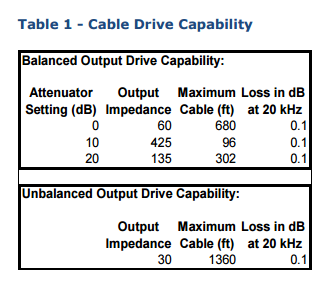
For grins:

From my DAC2 HGC Owners Manual:

2017-02-10_1934.png
 
I'd expect that subjective result from a long unbalanced cable, not from any FR droop at the top but purely because longer cables are more susceptible to common-mode noise. Roughly in direct proportion to their length. We don't hear the common-mode noise directly as its mostly ultrasonic, but it contributes to the IMD (or dynamic noise floor).

Good point, I hadn't thought of that but it makes sense.
 
Balanced avoids common-mode noise rather than cancels it. Cancellation suggests addition of equal but opposite noise which in practice is quite difficult to achieve accurately hence is only to be used if rejecting the noise in the first place can't be done for some reason...

Hi, Richard,

This is an interesting question. As Bill Whitlock of Jensen Transformers explains, an balanced interface is essentially a Wheatstone bridge, with any common-mode noise appearing as an A.C. voltage across the bridge. Any CM noise voltage appearing between the bridge's midpoint nodes is inherently converted to normal-mode and amplified by the input stage. However, if the bridge impedance terms are accurately matched there will be no noise voltage developed between the bridge's midpoint nodes. If there's no bridge midpoint CM noise voltage difference, there's no noise voltage converted to normal-mode and amplified by the input stage.

An balanced interface matches the common-mode noise amplitude appearing at each bridge arm midpoint node. The more accurate is the matching of the relevant CM impedance terms, the better is the noise cancellation or noise rejection or whatever it is properly termed as. I suppose that 'nulling' is as accurate an term as any, because matched bridge impedances ratios null midpoint node voltage.

The relevant impedance terms are those which appear to common-mode signals. These are usually different than those which appear to normal-mode signals as far as the input stage is concerned. Please feel free to correct anything which I may be overlooking, or which you feel is incorrect regarding this.
 
Last edited:
I'd expect that subjective result from a long unbalanced cable, not from any FR droop at the top but purely because longer cables are more susceptible to common-mode noise. Roughly in direct proportion to their length. We don't hear the common-mode noise directly as its mostly ultrasonic, but it contributes to the IMD (or dynamic noise floor).

My device that blocks the noise across SE is pretty easy to distinguish when it's inserted. Luckily it doesn't have any of the bad attributes that are common (not always present) with balanced/shield. Music is simply more pleasurable and clear. Anything good is only the same or better. The one condition is that it doesn't work if it's in between two things without safety earth on chassis (Sony and some other gear have 2-Prongs still).
 
This is an interesting question. As Bill Whitlock of Jensen Transformers explains, an balanced interface is essentially a Wheatstone bridge, with any common-mode noise appearing as an A.C. voltage across the bridge. Any CM noise voltage appearing between the bridge's midpoint nodes is inherently converted to normal-mode and amplified by the input stage. However, if the bridge impedance terms are accurately matched there will be no noise voltage developed between the bridge's midpoint nodes. If there's no bridge midpoint CM noise voltage difference, there's no noise voltage converted to normal-mode and amplified by the input stage.

Hi Ken, interesting discussion indeed. In what I wrote before I was being rather simplistic in that I was thinking that given we're not using the cable shield as our 0V reference there would be no CM currents to flow through it. Hence no need for any cancellation. But my view was indeed too simplistic as the CM currents in balanced mode induce a PD between the local 0Vs of transmitter and receiver. This PD is no longer in series with the wanted signal (as it was in the unbal case) but it does introduce a second-order effect via the (finite) CMRR of the receiver. Given the CMRR is finite, the rejection of the CM noise is indeed by cancellation rather than avoidance. So what I wrote is only correct to a first order.

There's also the somewhat more esoteric issue of cable transfer impedance which was touched upon in my EMC training classes many years back, but I still haven't gotten to the bottom of understanding this. In my partial understanding there is some way the CM currents in the drain wire can impose themselves on the wanted signal in the cable itself. Perhaps this is down to physical imperfections of the coaxial construction in that shields are normally braided so all the noise current doesn't in fact stay on the outside.

An balanced interface matches the common-mode noise amplitude appearing at each bridge arm midpoint node. The more accurate is the matching of the relevant CM impedance terms, the better is the noise cancellation or noise rejection or whatever it is properly termed as. I suppose that 'nulling' is as accurate an term as any, because matched bridge impedances ratios null midpoint node voltage.

It seems to me that the impedances are required matched for external electrostatic field rejection (since that's in effect parasitic capacitance to the signal wires) but as yet I'm unclear if impedance matching makes a difference to ground noise rejection. Certainly it can't harm but is there a benefit?

The relevant impedance terms are those which appear to common-mode signals. These are usually different than those which appear to normal-mode signals as far as the input stage is concerned. Please feel free to correct anything which I may be overlooking, or which you feel is incorrect regarding this.

Its looking to me you're more up to speed on the theory behind this than I so I'm enjoying the opportunity to brush up my own understanding here. Let me echo your own sentiments and ask for any corrections to my understanding.
 
Despite Don's patient and kind efforts I don't think we are there yet.


This is of what I am trying to get to the bottom.

Boy, Ron, the use of the apostrophe isn't the only grammatical concept about which you are obsessive.

I'm going to be very careful to never end a sentence with a preposition! ! !

Ooops, I used a split infinitive. Please forgive me!
 

About us

  • What’s Best Forum is THE forum for high end audio, product reviews, advice and sharing experiences on the best of everything else. This is THE place where audiophiles and audio companies discuss vintage, contemporary and new audio products, music servers, music streamers, computer audio, digital-to-analog converters, turntables, phono stages, cartridges, reel-to-reel tape machines, speakers, headphones and tube and solid-state amplification. Founded in 2010 What’s Best Forum invites intelligent and courteous people of all interests and backgrounds to describe and discuss the best of everything. From beginners to life-long hobbyists to industry professionals, we enjoy learning about new things and meeting new people, and participating in spirited debates.

Quick Navigation

User Menu

Steve Williams
Site Founder | Site Owner | Administrator
Ron Resnick
Site Co-Owner | Administrator
Julian (The Fixer)
Website Build | Marketing Managersing