Example Amplifier Responses into Speaker Loads

DonH50

Member Sponsor & WBF Technical Expert
Jun 22, 2010
3,947
306
1,670
Monument, CO
Showing the impact of speaker loading on amplifiers is not too hard but is tedious (at least it was for me!) I set up two amps and two speakers, then plotted the speaker impedance and frequency response at the amplifier terminals. The speakers were 8-ohm nominal, 3-way, with crossovers at 300 Hz and 3 kHz. The first amp is SS with 0.1 ohm output (damping factor of 80) rising to about 1 ohm (DF=12.5) at 20 kHz. This mimics the way a lot of amplifiers behave with rising output impedance with frequency. The second amp is a tube amp with 0.8-ohm output (DF=10) rising to about 4 ohms at 20 kHz (DF=2; this is about as bad as I have measured in the primordial past).

The top plot shows the impedance, the next the amplifier outputs, and in the bottom plot I repeated the first amplifier’s response and then showed differences from each other amplitude to that first (SS) amp.

AmplifierPlot4.JPG

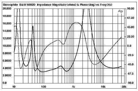
Speaker 1 shows pretty benign magnitude, with a slight dip where the midrange driver comes into play. The dip is because I used very simple first-order crossovers so there is some interaction among drivers. For the second speaker, I started with the network from the first, then added a roll-off at the high end to simulate a ribbon-type tweeter and a resonance dip to 4 ohms in the bass. This led to some peaks as well, though nothing terribly extreme.

Looking at the plots in the middle we can see how the amplifier’s impedances influence the response. A perfect amp would show a straight line. The SS amp into Speaker 1 (SS1, blue) shows very flat response with a bit of HF roll-off as expected. The tube amp into the first speaker (TUBE1, green) has a little less amplitude due to the higher impedance (this is insignificant since you’d just turn up the volume a little) and the HF roll-off kicks in sooner (again, expected for a tube amp). The plots into the second speaker are more interesting, with both amps showing some peaking at HF. This is because the rising output impedance is interacting with the capacitive load and causing a peak. Yes, this can happen in real life; it is one reason some amps are not stable with highly-capacitive loads. The peak is larger and at higher frequency with the SS amp (SS2, red) compared to the tube amp (TUBE2, light blue). This is because of the tube amps higher output impedance and faster HF roll-off. Note the tube amp into speaker 2 also has a LF dip, demonstrating the trouble it has driving low-impedance loads even at LF.

The final plot shows the SS amp into speaker 1, SS1 (blue), and the difference between that response and the other outputs. This is what we might hear when comparing amplifiers. Into the second speaker, the SS amp (red) is almost 3 dB higher at 20 kHz, peaking at ~5 dB at ~25 kHz, then rolling off. There is only about 1 dB difference at 10 kHz, rapidly decreasing to zero (a perfect match) below that. The tube amp into speaker 1 rolls off a little sooner, but is only about 1 dB down at 20 kHz, a difference we are unlikely to hear. Into the second speaker, the tube amp’s HF peak is about 4 dB at 15 kHz, dropping on either side. There is also that dip of ~1 dB at 30 Hz.

Can you hear this? I don’t know, but in a careful side-by-side test you might. Real amplifier and speaker impedances are more complicated and so might fare better or worse in a test. However, at least it shows that bad things can happen to good amps when presented with the real world of speakers.

HTH - Don
 

amirm

Banned
Apr 2, 2010
15,813
37
0
Seattle, WA
Excellent work as always. Maybe I can add more meat on the audibility of such frequency response variations. BTW, the same logic applies to speaker wire potentially causing similar variations but we digress :).

Turns out there is excellent work done in determining such variations with the interest being loudspeakers. Dr. Olive and Toole performed a number of listening tests trying to determine the effect of resonances back in 1988, published in their Journal of AES ("The Modi?cation of Timbre by Resonances: Perception and Measurement"). A Resonance is a peak in frequency response that is accompanied by "ringing" in time domain. Turned out the latter factor is not that important. What is important is that the frequency response is changing. The paper/research is extensive (I think they won a coveted AES Silver award for this work). The one bit that is related to this topic though is easy to digest from this graph (which is also included in Dr. Toole's excellent book, Sound Reproduction: Loudspeakers and Rooms):


The graph shows the threshold of detection based on the "Q" of the resonance. The Q simply states how sharp the peak is. The higher the Q, the taller and narrower the resonance. Shown here is the effect on both pink noise which was found to be most revealing and pop/voices which was found to not be as revealing. Classical music was in between.

We see that as the Q becomes smaller, the detection level shrinks. I.e. we are able to hear much smaller changes in frequency response variations. This may seem non-intuitive. But if you think about it, it makes sense. This is simply a game of statistics. If the Q is high and hence the variation range in frequency range small, chances of the music hitting on that exact set of tones/frequencies is smaller. The lower the chance, the lower the possibility of someone hearing it. Widen the Q and now a lot more notes will be varied and hence, detected. This is the reason classical music did better (i.e. was more sensitive to variations) than pop due to its and dense spectrum.

For low-Q variations, the detection level is just 0.5 db! So this comes down to the speaker and its impedance curve as Don also found. Adding both his post and mine together, the problematic speakers will be the ones that maintain their problematic impedance variations for wide range of frequencies. Here are some sample measured speaker impedances with tough drops to low amounts:


Don, are you able to plug any of these graphs into your model and see what spits out as far as measured deviation?
 

DonH50

Member Sponsor & WBF Technical Expert
Jun 22, 2010
3,947
306
1,670
Monument, CO
Thanks Amir, I keep thinking about renewing my AES membership but something else always comes up (like quarterly taxes the same month all our vehicle insurance is due!) How much of that is in Toole's book? I have it but have never got around to reading it all; I'll have to look up that section tomorrow.

I do not have any easy way to plug a curve into my model, but I need to delve into the behavioral elements in my Spice simulator. That might make it easier to plug in a reasonable approximation. Or see if JA would send me the raw data, then I could create a table-based source. I could play around to try to come up with elements that match the major peaks (essentially what I did this afternoon) but it is pretty tedious. Bottom line is that speaker loads do influence amplifier response. I was intrigued to find that SS varied a little more at HF and tubes a little less at LF in my model than I expected. It is a fairly simple model, but is a start.

For all, I used Q (quality factor) to calculate some of the values in my model (it is used when calculating resonant circuits, and I use them in the speaker 2 model). Q is used in many forms, but an appropriate one for Amir's post is Q = fc/BW where fc is the center frequency and BW is the bandwidth. This means high Q has very narrow bandwidth, thus we are less likely to hear a high-Q (narrow) spike in frequency response compared to a lower but much broader peak or dip (low-Q). We must also remember that "narrow" is relative to frequency.
 

amirm

Banned
Apr 2, 2010
15,813
37
0
Seattle, WA
Hi Don. The section in Dr. Toole's book is rather short (about a page) and is basically that graph. When I said to plug in those graphs, I just meant a few of the points to approximate them.
 

DonH50

Member Sponsor & WBF Technical Expert
Jun 22, 2010
3,947
306
1,670
Monument, CO
I'll have to see what is possible. I can make a piece-wise linear or tabular voltage or current source, but am not sure there is a similar way to make an arbitrary impedance, though it may be possible to gen up something. Have to think on it, and I'm tired tonight. It is something I have been thinking about off and on and now seems like a good time to dig deeper.

edit: Checking the element list, I can only create voltage-controlled voltage (E) and current (G) sources using behavioral models. However, I have built an impedance model using those sources and some circuit tricks in the past so might be able to do it again. Have to remember what the heck I did...
 

Raffles

New Member
Aug 12, 2012
64
0
0
UK
Hello DonH50. Nice work, but I have one query. You say
The second amp is a tube amp with 0.8-ohm output (DF=10) rising to about 4 ohms at 20 kHz (DF=2; this is about as bad as I have measured in the primordial past).

but I thought that tube amps routinely have much higher effective output impedance than this. A quick Google for tube amplifier output impedance comes up with measurements such as this (picked randomly from many)
http://www.stereophile.com/content/cary-audio-design-slm-100-monoblock-power-amplifier-measurements

Despite Cary's claimed high damping factor, the SLM-100's output impedance varied between 5.4 ohms and a very high 8.8 ohms, depending on the load impedance I used to assess the value. This very high output impedance will cause significant frequency-response deviations into real loads.

Or this one:
http://www.stereophile.com/content/vac-pa8080-power-amplifier-measurements

The output impedance was also high, at between 3.3 and 3.5 ohms (from the 8 ohm tap), depending on frequency. The system frequency response will thus be highly dependent on the loudspeaker load.

In one review, Stereophile says this:
...because loudspeaker impedances vary considerably with frequency, high output impedances result in significant modification of the amplifier's frequency response, due to the Ohm's Law interaction between the amplifier and loudspeaker impedances. This is illustrated by the gray trace in fig.1, which shows the DiaLogue Seven's frequency response from the 4 ohm tap in ultralinear mode into Stereophile's standard simulated loudspeaker. The response varies by up to ±2.1dB, which will be audible. From the 8 ohm tap (not shown), the response variation was ±3.2dB, which will be very audible.

When I measure amplifiers like PrimaLuna's DiaLogue Seven, my eyebrows always rise because the things they do wrong must be balanced against the possible sonic befits of the other things they do. Certainly, the designer's decision to use very high output impedances will drastically affect sound quality for reasons that are well understood. The DiaLogue Seven's measured performance in triode mode was notably worse than in ultralinear mode, yet Art Dudley ultimately preferred triode mode. A puzzle.
http://www.stereophile.com/content/primaluna-dialogue-seven-power-amplifier-measurements
 

JonFo

Well-Known Member
Jun 11, 2010
322
1
925
Big Canoe, GA
www.jonathanfoulkes.com
Don, great topic and well presented. This is an important aspect of overall system component selection and setup.

This is because the rising output impedance is interacting with the capacitive load and causing a peak. Yes, this can happen in real life; it is one reason some amps are not stable with highly-capacitive loads.

This resonated for me, as Electrostats have high capacitance as well as wild impedance swings. Paired with the wrong kind of amp ( most tubes ), they can perform poorly, as the amp can't deliver the current needed and the system will have severe frequency deviations due to low DF.

One way of mitigating the challenges is reduce the number of components in the system that induce impedance swings and/or additional capacitance. So all my ESLs have their passive crossovers removed and I drive the panels directly ( through the ESL step-up transformer) with a high-current SS amp.

I agree with your premise that amp/speaker interaction can have a significant effect on the resulting sound and that understanding the underlying nature of those interactions is critical to guiding and optimizing the selections one makes.
 

DonH50

Member Sponsor & WBF Technical Expert
Jun 22, 2010
3,947
306
1,670
Monument, CO
Hello DonH50. Nice work, but I have one query. You say
...
but I thought that tube amps routinely have much higher effective output impedance than this. A quick Google for tube amplifier output impedance comes up with measurements such as this (picked randomly from many)
http://www.stereophile.com/content/cary-audio-design-slm-100-monoblock-power-amplifier-measurements

..rest elided...

As I said, it is an example, based on my memory of the output impedance of my old ARC D79 if you must know. Unfortunately, there are many, many different amps and speakers and I do not have the time to simulate them all even if I had appropriate models for them (making the model is most of the work). I may try to run a couple of more examples with higher-impedance amps and different speakers, but my time for this exercise, interesting as it is, is finite. That's the problem with these sorts of exercises; do one, and there are a hundred equally interesting other cases to try. That said, I would like to try one with higher Zout and lower speaker dips; I think I can do those fairly easily whilst watching football this afternoon. We'll see.

On the question of higher damping factor, depending on whom you read once you get over 20 or so it does not matter, and over 100 is almost certainly overkill. A DF of 1000 into 8 ohms is an impedance of 0.008 ohms, a number that will likely be swamped by the wires from amp to speaker. You can see in my simple model that a DF of 80 provides essentially no variation (until HF when the DF drops in my model).

One reason for wide band amps is they should hold higher damper factor (lower output impedance) higher in frequency. Audible? Only you can say for sure...
 

DonH50

Member Sponsor & WBF Technical Expert
Jun 22, 2010
3,947
306
1,670
Monument, CO
Don, great topic and well presented. This is an important aspect of overall system component selection and setup.

This resonated for me, as Electrostats have high capacitance as well as wild impedance swings. Paired with the wrong kind of amp ( most tubes ), they can perform poorly, as the amp can't deliver the current needed and the system will have severe frequency deviations due to low DF.

One way of mitigating the challenges is reduce the number of components in the system that induce impedance swings and/or additional capacitance. So all my ESLs have their passive crossovers removed and I drive the panels directly ( through the ESL step-up transformer) with a high-current SS amp.

I agree with your premise that amp/speaker interaction can have a significant effect on the resulting sound and that understanding the underlying nature of those interactions is critical to guiding and optimizing the selections one makes.

Thanks!

On electrostats, I tend to agree. Great as the midrange sounds, the high capacitive loading of 'stats made the tube amps I tried on them (several models of amps and 'stats) not sound good to me. I have tried direct-coupling to the panels through a dc block from a differential output stage to eliminate the transformer but it was a lot of work...

One of the 'stat designers (Roger?) states directly tubes and 'stats are a bad match. Brave man!
 

Raffles

New Member
Aug 12, 2012
64
0
0
UK
As I said, it is an example, based on my memory of the output impedance of my old ARC D79 if you must know.

Sorry to have been so picky, but it's just that your post implied that 0.8 (rising to 4) ohms was the worst we were likely to encounter, and people seem to have gone away thinking that there is nothing to worry about. Yet it looks as though real world results with many (most?) tube amps could be much worse than your model suggests.
 

DonH50

Member Sponsor & WBF Technical Expert
Jun 22, 2010
3,947
306
1,670
Monument, CO
Sorry to have been so picky, but it's just that your post implied that 0.8 (rising to 4) ohms was the worst we were likely to encounter, and people seem to have gone away thinking that there is nothing to worry about. Yet it looks as though real world results with many (most?) tube amps could be much worse than your model suggests.

I was hoping to do something quick so used what I knew; we depend upon folk like you with time to check things and keep us straight. You are of course free to run your own simulations using your own models, but my next post should help...
 

DonH50

Member Sponsor & WBF Technical Expert
Jun 22, 2010
3,947
306
1,670
Monument, CO
Here are a new set of plots to address some of the comments made earlier. The SS amp now has a LF damping factor (DF) of 200 (0.04 ohm output) dropping to 50 (0.16 ohms) at 20 kHz. The tube amp went the other way, with an output impedance of 4 ohms (DF = 2) rising to 6 ohms (DF = 1.33) at 20 kHz.

There are no changes to speaker 1, still a pretty tame 8-ohm load, or speaker 2, dipping to 4 ohms at 40 Hz and ~3 ohms at 20 kHz (with a few other peaks and valleys). I added another speaker (3) that dips all the way to 2 ohms at 40 Hz, a milder HF load (~5 ohms at 20 kHz), but adds a high-Q peak around 1.5 kHz that raises the impedance to about 22 ohms.

AmplifierPlot5a.JPG

Now the SS amp performs pretty well into every speaker, though the low HF impedance of speaker 2 still reacts with the output inductance to peak 1.5 dB way up at 70 kHz (only ~0.25 dB at 20 kHz). The lower LF impedance dip of speaker 3 causes a very small dip, about 0.1 dB.

The tube amp struggles due to the much higher output impedance of the new model. It is OK with speaker 1 (have I mentioned how much I like my Magnepans?) but struggles with speaker 1 and 2.

This repeats work I did long ago, and no doubt done by many, many others. It helps explains my position on amps, which is that for most speakers I find it easy to distinguish a SS from a tube amp, find it almost impossible to pick from two SS amps at reasonable levels, and find it much harder to pick between two tube amps (though IME tube amps tend to vary much more than SS amps). This also helps explain why some people prefer certain amp/speaker pairings.

HTH - Don
 

JonFo

Well-Known Member
Jun 11, 2010
322
1
925
Big Canoe, GA
www.jonathanfoulkes.com

DonH50

Member Sponsor & WBF Technical Expert
Jun 22, 2010
3,947
306
1,670
Monument, CO
Thanks. I first met Roger many years ago and I am sure he would not remember me (young kid at the time), but I would like to get up to his place sometime since he's relatively close now.

I'll have to read the thread, but IME the big problem is the same as any other speaker: tube amps using transformer-coupled outputs (most of them) do not work well with impedances that stray too far from the nominal tap impedance. Conventional speakers vary all over but the largest excursions tend to be narrow'ish. An electrostatic speaker is essentially a big capacitor and has relatively high impedance (50 - 100 ohms or more) at LF and dropping to very low (often only 1 - 2 ohms) at HF. That is a huge range for a tube amp to drive.
 

ack

VIP/Donor & WBF Founding Member
May 6, 2010
6,774
1,198
580
Boston, MA
It's worth repeating the more salient and relevant to this discussion points from Mr. Sanders' excellent posts:

There is one more detail to bring up in this quest for a low Q woofer, and that is the effect that passive crossovers have on amplifier damping. Understand that the Theil-Small parameters consist of Qms, Qes, and Qts. Qms refers to the mass of the driver. It is considered to be the mechanical Q of the speaker and is determined by the mass of the moving parts of the speaker and the behavior of the suspension system.

Generally, for a given suspension, the higher the mass, the more the driver will tend to overshoot and ring. For a given mass, the softer the suspension, the less the driver will overshoot and ring. In other words, a low Qms woofer will have low mass and a very soft suspension. These factors will also reduce its free air resonance point.

Qes refers to the electrical Q. Understand that when you move the voice coil through its permanent magnetic field, an electrical current will be generated in the voice coil. If you place a load across the voice coil, this current will do work. Work requires energy. The energy comes from the motion of the woofer cone.

If you short out the voice coil, the most energy will be required from the woofer cone. If you leave the voice coil as an open circuit, no energy will be required from the woofer cone.

You can easily feel this. Just disconnect a speaker from its amplifier, then push the woofer cone back and forth with your fingers as you alternately open and short across the speaker binding posts. You will clearly feel a resistance to the woofer's motion when you short the voice coil.

This is electrical damping. It becomes greater if the permanent magnet is more powerful.

Qes is highly desirable. It is at its best when the woofer is connected directly to a very low impedance amplifier. The "damping factor" is the ratio between the impedance of the voice coil and the amplifier's output impedance.

For example, if you have an 8 ohm voice coil in your woofer and you connect it to the 8 ohm taps of a tube amplifier, the damping factor will be 1 (one). If that same 8 ohm voice coil is attached to a powerful solid state amplifier whose output impedance is 0.02 ohms (a typical value), then the damping factor would be 400. The lower Q of the solid state amp system causes the bass to sound "tighter" than from most tube amps.

I have simplified the damping factor issue somewhat because I did not mention global feedback. Suffice it to say that global feedback incorporates the speaker load into the feedback loop and significantly increases the damping factor of an amplifier. So a moderate amount of global feedback is very helpful at controlling the woofer's motion.

It is very important to note that the addition of any series resistance between the woofer and the amplifier will tremendously degrade the damping factor. This is where passive crossovers are so evil. They always have one or more inductors in series with the woofer.


To strengthen the last point, going from inductors measuring 1.5ohms to Mundorfs measuring 0.1ohms had a very positive effect in my crossover redo.


DonH50

Member Sponsor & WBF Technical Expert
Jun 22, 2010
3,947
306
1,670
Monument, CO
Thanks ack. I have long held the opinion that the biggest change in (passive) crossovers is made by swapping out the inductors. Much more impact IME than all the fiddling I have done to improve the capacitors. And highlights why active designs without passive crossovers (which I believe Roger is using) can sound better.
 

ack

VIP/Donor & WBF Founding Member
May 6, 2010
6,774
1,198
580
Boston, MA
Thanks ack. I have long held the opinion that the biggest change in (passive) crossovers is made by swapping out the inductors. Much more impact IME than all the fiddling I have done to improve the capacitors. And highlights why active designs without passive crossovers (which I believe Roger is using) can sound better.

I was sold on external crossovers decades ago with the DQ-10 (though there was still a passive crossover in the main upper unit), and the Entec sub I still use in another system. They just won't work with Spectral in my case. But capacitors can also make a huge difference in terms of clarity and transparency and also affect damping, as: a) the better ones charge and discharge faster = less smearing; b) stacking them up in parallel reduces their in-series resistance (which is what I also did). I heard changes with both inductors and capacitors, and I upgraded one series after the other to be sure of the results.
 

DonH50

Member Sponsor & WBF Technical Expert
Jun 22, 2010
3,947
306
1,670
Monument, CO
Hmmm... Whilst I have as many opinions as the next guy, I would prefer to take capacitor discussions as well as debating Roger's thoughts into a different thread and keep this one focused on just the technical results. That is sort of our goal for this part of WBF (with mixed success I admit!)
 

assessor43

Well-Known Member
Nov 1, 2018
312
194
128
Don, great topic and well presented. This is an important aspect of overall system component selection and setup.


This resonated for me, as Electrostats have high capacitance as well as wild impedance swings. Paired with the wrong kind of amp ( most tubes ), they can perform poorly, as the amp can't deliver the current needed and the system will have severe frequency deviations due to low DF.

One way of mitigating the challenges is reduce the number of components in the system that induce impedance swings and/or additional capacitance. So all my ESLs have their passive crossovers removed and I drive the panels directly ( through the ESL step-up transformer) with a high-current SS amp.

I agree with your premise that amp/speaker interaction can have a significant effect on the resulting sound and that understanding the underlying nature of those interactions is critical to guiding and optimizing the selections one makes.
Your comments are exactly why I started this thread.
 

About us

  • What’s Best Forum is THE forum for high end audio, product reviews, advice and sharing experiences on the best of everything else. This is THE place where audiophiles and audio companies discuss vintage, contemporary and new audio products, music servers, music streamers, computer audio, digital-to-analog converters, turntables, phono stages, cartridges, reel-to-reel tape machines, speakers, headphones and tube and solid-state amplification. Founded in 2010 What’s Best Forum invites intelligent and courteous people of all interests and backgrounds to describe and discuss the best of everything. From beginners to life-long hobbyists to industry professionals, we enjoy learning about new things and meeting new people, and participating in spirited debates.

Quick Navigation

User Menu

Steve Williams
Site Founder | Site Owner | Administrator
Ron Resnick
Site Co-Owner | Administrator
Julian (The Fixer)
Website Build | Marketing Managersing