The purpose of this thread is to provide a quick introduction to digital-to-analog converters (DACs), the magical things that turn digital bits into analog sound. Previous threads have discussed sampling theory, aliasing, and jitter. Now we’ll get down to the hardware and take a look at some basic DAC architectures.
The two criteria most often used to describe a DAC are its resolution (number of bits) and sampling rate (in samples per second, S/s, or perhaps thousands of them, kS/s). If we think about producing an analog output both of these are important. The resolution determines the dynamic range (in dB) of our DAC, and sampling speed determines how high a signal can be output. As discussed in those earlier threads, resolution sets an upper limit on signal-to-noise ratio (SNR) and spurious-free dynamic range (SFDR, the difference between the signal and highest spur). For an ideal (perfect) DAC, we can find:
SNR = 6.021N + 1.76 dB; and,
SFDR ~ 9N; where N = the number of bits.
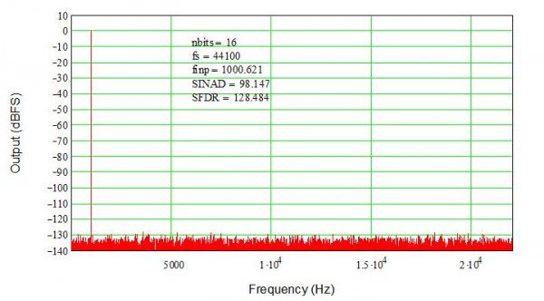
While not terribly difficult to prove, I shan’t delve into the math here. For that, and the definitions of numerous other specifications (and how they are tested), pick up a copy of the IEEE’s Standard 1241 for ADCs. Plugging in, for a 16-bit DAC, SNR ~ 98 dB and SFDR ~ 144 dB. Figure 1 shows the output in the first Nyquist band from a perfect 16-bit DAC with a 1 kHz input signal sampled at 44.1 kHz. The SFDR (noise floor) is “only” about 130 dB because I did not use an infinite number of data points (samples) in the simulation (only 65,536). The signal-to-noise-and-distortion ration, SINAD, is essentially ideal, so it’s close enough (and I do not have infinite time to wait for a simulation of infinite points to finish!) SINAD is the same as SNR for an ideal DAC, and is used to calculate actual performance for the rest of this article (matching the IEEE Standard).
For sampling rate (frequency) Fs the maximum input signal frequency to an ADC is strictly < Fs/2 to prevent aliasing (folding of the signal around Fs/2 to a lower frequency; see the sampling thread for more about why). It is important to note that, while a DAC cannot be driven by a signal >= Fs/2, it can produce output signals higher than that. In fact, the signals from Fs/2 will be replicated at all multiples of Fs/2, producing a wide range of output signals. It is probably easiest to think of this as the opposite of aliasing in an ADC; at the output of a DAC, images occur at multiples of Fs/2. There are of course other less desirable outputs, also broadband, such as glitches, ringing, distortion, clock feed through, and other spurious products. For now, just remember everything equal to and above Fs/2 is squashed back into the audio baseband (d.c. to Fs/2) by an ADC, while a DAC generates a series of images of the baseband multiplied up by Fs/2.
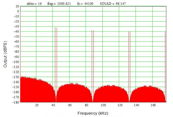
Figure 2 shows what the output images look like from the simulation above. Note how the signal is replicated (imaged) around each Fs/2 segment (the even multiples are mirror-imaged so we see signals just below and just above multiples of Fs/2, i.e. at M*Fs/2 +/- 1 kHz where M = 0, 1, 2,…). Whether an ADC or a DAC, aliasing/imaging means frequency information is lost – there’s no way to tell the intended frequency, input or output, after it’s sampled and aliased. However, RF systems take advantage of those DAC images by using bandpass filter to select an upper image and eliminate a mixer.
Note that the amplitude rolls off in the images, and there are notches (nulls, zero inflection points) at each multiple of the sampling frequency (44.1 kHz). It’s in the math which I’m trying to minimize, so trust me – it’s correct. Technically, it follows a sinc (sinX/X) envelope. Furthermore, it’s easy to show that at the Nyquist frequency (Fs/2) the output is actually down -3.54 dB. We don’t measure this roll-off in commercial audio DACs because peaking filters (or other techniques not discussed here) are used to flatten the response. Analog output filters are used to roll off any signals and noise above about 20 kHz so you will not see these images at the output of a commercial audio DAC. Not without some serious test equipment, anyway…
Most people here probably understand how a conventional Nyquist DAC functions, at least to a hand-waving level. A 16-bit DAC resolves 2^16 (65536) levels, each of which is generated by the DAC’s internal circuits. For a 1 Vpp output, that means the least-significant bit (lsb) is only ~15 uV. Any errors in the DAC’s levels will cause distortion at the output. With a fully unary 16-bit DAC, using 65,536 individual (unit) cells to create the levels, each cell need only have error < 50 %. However, such a large number of cells requires a lot of area and thus is expensive to make. That many cells also present a significant load at the output, reducing bandwidth. In contrast, a binary DAC needs only 16 cells, with weighted values [2^15, 2^14,… 2^0]. While this seems much simpler, the most-significant bit (MSB) must match the lower bits to the 16-bit level (0.00153 %) to prevent errors when switching from lsbs to the MSB. Achieving such high precision is very challenging, requiring calibration and trimming that is again expensive and difficult to maintain over time, temperature, power supply variations, etc.
Typical real-world DACs are segmented into unary and binary sections. For instance, a 16-bit DAC with the upper six bits unary and remainder binary requires only 1/2^6 (1/64) the precision of a binary design in the upper bits, or error < 0.1 %. This is still quite challenging but much easier to achieve and maintain than 0.0015 %, and provides a compromise between performance and complexity. There are 64 MSB cells with a weight of 1024, and then 10 binary lsbs bits weighted [1, 2, 4,…512]. When all the lsbs are ON, they sum to 1023, thus the 10 lsbs fill in all the steps between the MSBs. The net number of steps is 64*1024 = 65,536 as expected for a 16-bit DAC (2^16 = 65,536).
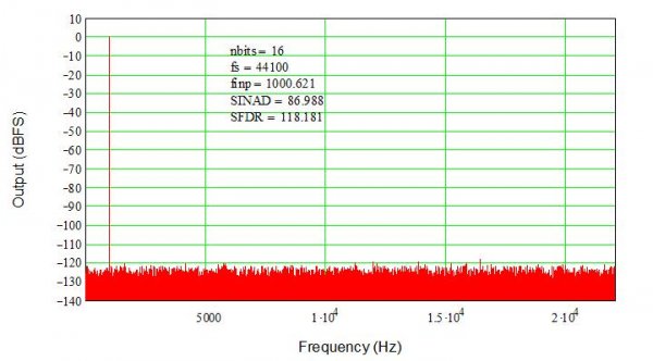
Errors have been discussed before but it’s time to touch upon them again. Jitter is discussed in other threads so we’ll only look at amplitude errors now. Figure 3 again shows the 16-bit unary DAC, but this time 1-lsb standard deviation random (normal distribution) errors have been added to the thresholds. Note that the noise floor looks the same but is higher, and SINAD has degraded from 98 dB to 87 dB. For each additional increase in noise by 1 lsb (standard deviation) we’ll lose another 6 dB in SINAD.
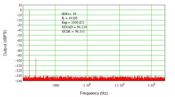
An interesting experiment is to add a slight (1-lsb peak) bow to the DAC thresholds. This models a gradient with the endpoints (min/max DAC values) having zero error and the center code having a 1-lsb error with a smooth (parabolic, x^2) curve from the ends to the center. This is a very slight error, but because it is not random it generates a significant distortion term, in this case second harmonic distortion (2HD) The frequency response in Figure 4 uses the same parameters as in Figure 1. The noise floor is as before for the ideal DAC, but notice the 2HD spur is only 96 dB down, or about 30 dB above the noise floor. This is well below what we can hear, of course, but highlights how even very small errors can be a problem if they are correlated (deterministic) rather than random. The 2HD spur will rise an additional 6 dB for each 1-lsb increase in error (e.g. a 2-lsb bow will introduce a 90 dB 2HD spur).
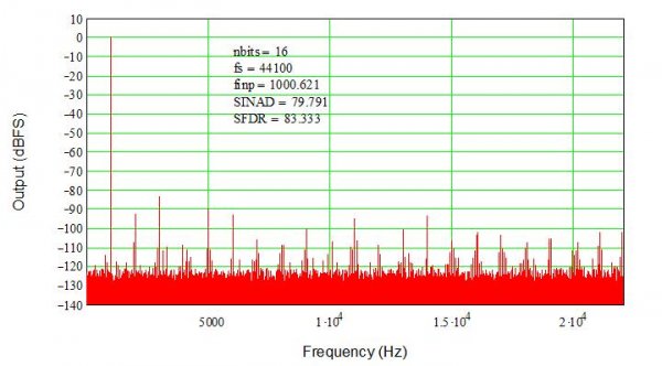
A segmented DAC may have higher distortion because segmentation introduces patterns (correlation). This is the trade for reduced complexity (and lower power, etc.) For example, the 6/10-bit segmented DAC has 2^6 = 64 upper (MSB) cells each weighted by 1024. In between, the 10 lsbs fill in the 1023 steps between the upper cells, creating a continuous range of steps from 0 to 65,535. However, since the codes occur in segments between MSB steps, those 1024 lsb steps are repeated (64 times) over the DAC’s full-scale range. Adding 1-lsb errors creates a repetitive pattern, leading to correlated errors and thus higher distortion spurs. Since there are 64 segments, we expect a series of spurs, not just a single spur such as we saw with a simple bow error. And, that’s just what Figure 5 shows. The individual errors are still random, still 1-lsb standard deviation, but because the segments are repeated a series of spurs results. The largest is only 83 dB down; still in audible, but again it’s clear that just a few lsbs of error can create significant distortion in the DAC’s output. Furthermore, the combination of higher noise floor and spurious products has reduced SINAD to 80 dB, equivalent to about a 13-bit DAC (we have lost three bits of resolution).
One thing not discussed is the output filter. Ideally, assuming a 20 kHz output bandwidth, then any spurious products must be suppressed to below the DAC’s noise floor, or at least below the SINAD (i.e. by 98 dB for a 16-bit DAC). Looking at the distortion plots one might think this isn’t terribly challenging as long as the DAC is pretty linear. However, there are those pesky images to consider. Remember, any output is imaged (or “mirrored”) around Fs/2. This means a 20 kHz output signal has an image at about 24 kHz for a 44.1 kS/s DAC. While unlikely in practice, designers must assume that users may in fact output a full-scale 20 kHz signal, requiring that 24 kHz image to be suppressed by more than 98 dB. That takes a very, very steep (high-order) filter. Unfortunately, very high-order filters tend to have high phase shift, ringing, amplitude ripples, and other artifacts at frequencies well below their cut-off, i.e. well into the audio band. This is the oft-discussed filtering problem non-oversampled (NOS) DACs face.
The next thread will explore oversampling and DAC architectures that take advantage of oversampling to improve their performance and simplify their filter requirements.
Last edited:


