SET amp owners thread

Here is the link for the whole thread regarding upgrades on theese amps;


And this is the schematics for the upgraded amp.

View attachment 116038
Thanks.
Its not a good idea to run the power tube without a stopping resistor. 150 Ohms will work better than 10K!
The 47 Ohm resistor should be bypassed to ground at its output else it will generate noise in the power supply. If it were me I would simply get rid of it.
The input tubes should each have a grid stopping resistor. 1.5K is adequate. You may notice a lower noise floor. Also, there should be a small resistance of 50 Ohms or so (matched) in series with each cathode of the input tubes to prevent current hogging, since they are in parallel. Otherwise distortion will be higher! You may notice greater clarity once this is corrected.
There clearly is a bit of compensation going on about the coupling cap. Did anyone explain to you what this is for? The answer to this question is important- it appears the compensation is for something, a deficiency somewhere.

I really don't think the grid choke is a good idea. Chokes are inductors and so at some low frequency they have a low impedance as well! If low frequency noise is able to pass thru the input stage, the low impedance presented will cause the voltage amplifier/driver to make additional distortion. Its hard to imagine how that's a good thing. So to use it, you'll want a low frequency filter of some sort (based on the cutoff frequency the choke and the caps present) to make sure the voltage amplifier/driver does not see any low impedances on account of this property. That filter does not appear to be the coupling cap array, which has a pretty high capacitive value!! So I'm really wondering how this is supposed to work. Usually you want to keep the coupling cap value as low as possible, so as to prevent coloration from the part itself, so long as you satisfy all your low frequency bandwidth requirements.
Ralph, have you heard the original Lamm ML2 with an easier speaker load say, 16 ohms and 105dB? I ask because I have read your posts which suggest such SET amplifiers sound best when using less than 10% of their power rating for lowest distortion.
Our shop speaker is 16 Ohms and very easy to drive. We usually are running less than 4 Watt peaks on them, well withing the 20-25% range I've commented about in the past. Our amps have meters so we can see how much power is being made.
 
Thanks.
Its not a good idea to run the power tube without a stopping resistor. 150 Ohms will work better than 10K!
The 47 Ohm resistor should be bypassed to ground at its output else it will generate noise in the power supply. If it were me I would simply get rid of it.
The input tubes should each have a grid stopping resistor. 1.5K is adequate. You may notice a lower noise floor. Also, there should be a small resistance of 50 Ohms or so (matched) in series with each cathode of the input tubes to prevent current hogging, since they are in parallel. Otherwise distortion will be higher! You may notice greater clarity once this is corrected.
There clearly is a bit of compensation going on about the coupling cap. Did anyone explain to you what this is for? The answer to this question is important- it appears the compensation is for something, a deficiency somewhere.

I really don't think the grid choke is a good idea. Chokes are inductors and so at some low frequency they have a low impedance as well! If low frequency noise is able to pass thru the input stage, the low impedance presented will cause the voltage amplifier/driver to make additional distortion. Its hard to imagine how that's a good thing. So to use it, you'll want a low frequency filter of some sort (based on the cutoff frequency the choke and the caps present) to make sure the voltage amplifier/driver does not see any low impedances on account of this property. That filter does not appear to be the coupling cap array, which has a pretty high capacitive value!! So I'm really wondering how this is supposed to work. Usually you want to keep the coupling cap value as low as possible, so as to prevent coloration from the part itself, so long as you satisfy all your low frequency bandwidth requirements.

Our shop speaker is 16 Ohms and very easy to drive. We usually are running less than 4 Watt peaks on them, well withing the 20-25% range I've commented about in the past. Our amps have meters so we can see how much power is being made.

Thank You for this very detailed answer @Atmasphere, highly appreciated.

These amps of mine are not identical to neither the original, nor the upgraded versions of the M500, as from the link where TL describes his work. My amps turned out to be modified/changed by someone I am not familiar with (found out after I purchased them). Hence, the schematics is not perfectly accurate. I am trying to track down who made the modifications here in Norway to see what has been done and if that person made any notes and/or schematics.

I will definitely look in to the things You highlighted in your post above and see if I can have them done.
 
Thanks.
Its not a good idea to run the power tube without a stopping resistor. 150 Ohms will work better than 10K!
The 47 Ohm resistor should be bypassed to ground at its output else it will generate noise in the power supply. If it were me I would simply get rid of it.
The input tubes should each have a grid stopping resistor. 1.5K is adequate. You may notice a lower noise floor. Also, there should be a small resistance of 50 Ohms or so (matched) in series with each cathode of the input tubes to prevent current hogging, since they are in parallel. Otherwise distortion will be higher! You may notice greater clarity once this is corrected.
There clearly is a bit of compensation going on about the coupling cap. Did anyone explain to you what this is for? The answer to this question is important- it appears the compensation is for something, a deficiency somewhere.

I really don't think the grid choke is a good idea. Chokes are inductors and so at some low frequency they have a low impedance as well! If low frequency noise is able to pass thru the input stage, the low impedance presented will cause the voltage amplifier/driver to make additional distortion. Its hard to imagine how that's a good thing. So to use it, you'll want a low frequency filter of some sort (based on the cutoff frequency the choke and the caps present) to make sure the voltage amplifier/driver does not see any low impedances on account of this property. That filter does not appear to be the coupling cap array, which has a pretty high capacitive value!! So I'm really wondering how this is supposed to work. Usually you want to keep the coupling cap value as low as possible, so as to prevent coloration from the part itself, so long as you satisfy all your low frequency bandwidth requirements.

Our shop speaker is 16 Ohms and very easy to drive. We usually are running less than 4 Watt peaks on them, well withing the 20-25% range I've commented about in the past. Our amps have meters so we can see how much power is being made.
I had to read the whole thread in diyaudio to refresh my memory on this set of mods, it is some time ago...... and TL was a force on there for a number of years.

The 47 ohm resistor in the ht line is shunted, but by the WE / Ultrapath cap connecting the ht to the filament of the 300B. Apparently the "trick" to getting this right is the magic ratio of 3.2 between the WE / Ultrapath cap and the filament bypass cap. This approach has its advocates, and John Broskie ran a detailed analysis of it on Tubecad, concluding that if you want you use it, fitting it to 2 stages is better than one.

I would agree about the 300B snubber.

The grid choke will create an LF resonance with the small coupling capacitor, as discussed by TL in the diyaudio thread this can be several dB is size! The "fix" is to add the snubber circuit across the coupling cap, named DR.P (?) to try to counter this.

I have no doubt both mods are audible, and both have vocal advocates, it will be interesting to hear what @crosswind thinks of them once implemented and run in.
 
The grid choke will create an LF resonance with the small coupling capacitor, as discussed by TL in the diyaudio thread this can be several dB is size! The "fix" is to add the snubber circuit across the coupling cap, named DR.P (?) to try to counter this.
I suspected that was what is was for. The thing about that: you can count on frequency response to be uneven as the network won't compensate the resonance exactly.

SETs are tricky because being zero feedback, everything in them makes a difference. They also have limited power and bandwidth. To me it make no sense to mess with anything that might limit FR and/or cause FR aberrations. Being zero feedback, with many speakers its already quite likely to get a bit too much bass energy at the resonance of the speaker in the box owing to the fact that the speaker is designed for the amp to be constant voltage, while the amp is more like 'constant power'; adding to that a coupling system that might add resonance seems sketchy at best.
 
  • Like
Reactions: sjs
I suspected that was what is was for. The thing about that: you can count on frequency response to be uneven as the network won't compensate the resonance exactly.

SETs are tricky because being zero feedback, everything in them makes a difference. They also have limited power and bandwidth. To me it make no sense to mess with anything that might limit FR and/or cause FR aberrations. Being zero feedback, with many speakers its already quite likely to get a bit too much bass energy at the resonance of the speaker in the box owing to the fact that the speaker is designed for the amp to be constant voltage, while the amp is more like 'constant power'; adding to that a coupling system that might add resonance seems sketchy at best.
Agreed, not an approach I would be looking to implement tbh
 
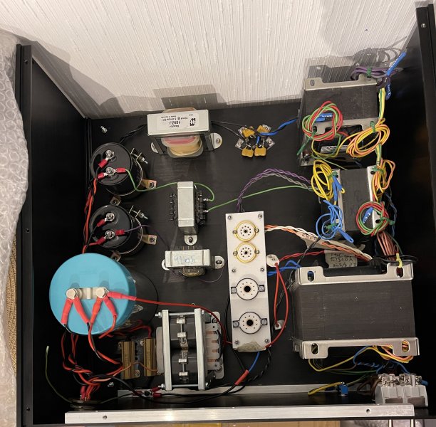
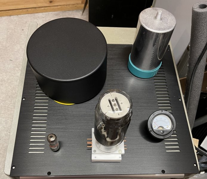
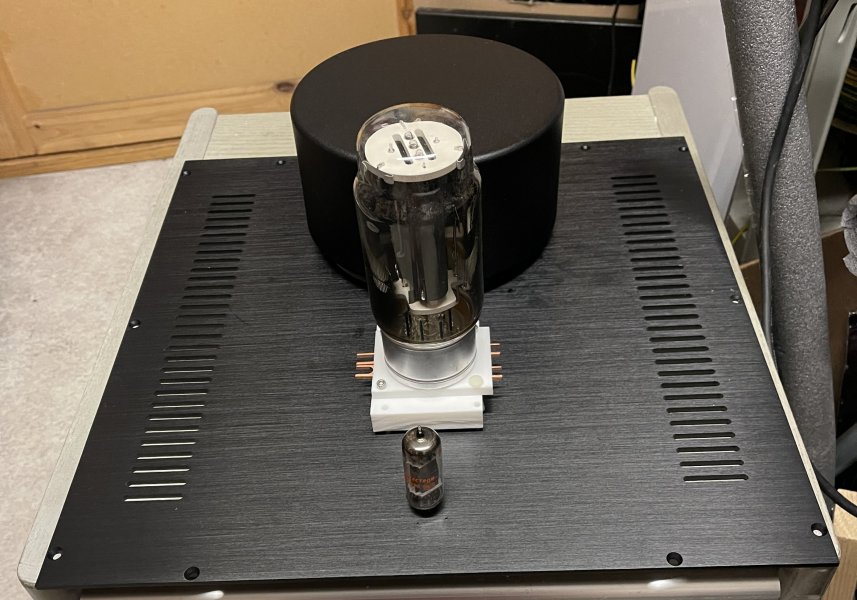
driver 6DE7, but can also use 6s45pi
interstaged to GM-70
Menno van der Veen toroid OPT
rectifiers EZ80 for bias and driver HV and EY500A for GM70
Interesting design! My Silvercore 2A3 amp uses a transformer coupled 6S45P stage and 5U4G or 5AR4 for rectifier. Output iron is Silvercore.
 
Interesting design! My Silvercore 2A3 amp uses a transformer coupled 6S45P stage and 5U4G or 5AR4 for rectifier. Output iron is Silvercore.
In this design, the GM70 mode is more interesting. It can give a more or less satisfactory sound at a supply voltage of more than 1.2-1.3 kV. In this mode, the 6S45P should supply at least 150V to the GM70 grid, but the maximum plate voltage for it is normalized to 150V, that is, it can actually get about 50V without big distortion. By the way, it may not be enough for 2A3 either. For high plate voltage 2A3, and in this mode it sounds best.
 
Last edited:
D3a tube 170-180V bias 18-20mA interstage Bartolucci INT8C
gm 70 1100V 90mA
 
1100V is bit better than 1000V for GM70. But the supply voltage for the driver should be 600-700V. I would recommend you to try EL803 (EL83) or 6AG7 in triode mode. I like EL803 Telefunken or Tesla with gray lettering.
actually it is 1100
first I´ll build it as Gary designed it....
 
A couple of SET updates:

I have reacquired an Ayon Crossfire III and use my Marconi 5U4G in the rectifier position. The sound with the Horning Eufrodites is superb! It has most of the qualities of the Amplifon SET42SE but with "looser hips". Transparency, soundstage precision and depth are truly excellent. Interestingly, it has very powerful but well controlled bass and dynamics are simply huge...the biggest of any amp I have tried so far on the Horning speakers.


The Horning SATI has been upgraded with Sylvania NOS VT-231 input/driver tubes and NOS Sylvania 5U4GB rectifiers. This amp now has (compared to the Soviet recitifiers) much better tonality and grunt as well as superb texture in the mid and bass region. Transparency is very good but perhaps a slight step behind the Ayon and Silvercore. Dynamics are similar to Silvercore but clearly behind the Ayon. Bass power is more than good enough though and it has an overall richer/warmer sound than the Ayon or Silvercore. That said it is nicely balanced and doesn't go too far or sacrifice (much) transparency for a slightly friendlier sound. I would say this amp is really well suited to smaller music where intimacy is desired and the Ayon is more suited to more eclectic music or classical music where you want more "hear into" qualities and dynamic swings.

These are of course tendencies rather than one amp is good for one thing and the other is good for something else. I am talking subtleties here but I think you know what I mean.

Overall, the Silvercore is probably still the best balance, falling nicely between these other two amps and makes me want to try something like a Kondo Souga or Wavac EC-300B on these speakers...to see if what the Silvercore does right can be taken to the next level.

Given what I paid for the Silvercore amp, it is one of the best bargains I ever made with regard to sound return on investment...
 
  • Like
Reactions: AudioHR and cal3713
Same old tune. As @SVS said, our ears tell us different rectifiers can sound different. That’s certainly true in my experience and it’s not just due to voltage drop. I don’t know why there is such resistance on this. Is there any doubt signal tubes that measure the same sound different? Everything matters. But as I have said a number of times, for those who think rectifiers of the same type sound the same, that’s fine, just leave the vintage NOS tubes for the rest of us.
Have you ever compared the sound from the equally applicable 5U4G, 274B and 5AR4 rectifiers? I need help making a choice, am looking for realism with a nod towards the romantic.
 
Have you ever compared the sound from the equally applicable 5U4G, 274B and 5AR4 rectifiers? I need help making a choice, am looking for realism with a nod towards the romantic.
Where are you using the rectifier—-power amp, preamp, DAC? Is the power supply choke input or cap input?

These issues matter. For low current supplies with cap input filtering, I like to use 5R4GY because of it has such a clean, detailed transparent sound. The only disadvantages are it’s a little lean in the lower midrange and not the last word in dynamics. For choke input supplies the 5R4GY is even better; it’s just as clean and detailed but not lean or restrained in dynamics.

For power amps with cap input supplies I use 5U4GB. It has a solid, robust and direct sound. I have only tried one type of 5U4G—-RCA from the ‘50s—-but it doesn’t have as strong bass as RCA 5U4GB from the ‘60s. Perhaps other 5U4G tubes would sound better but my experience with the RCAs hasn’t encouraged me to try others.

The only 274B I have is a modern Sophia blue bottle. It doesn’t sound bad but I prefer the 5R4GY.

I have no use for the 5AR4 or other indirectly heated rectifiers. I have several Mullard 5AR4s from my ST70 days way back when but they sound too veiled to me.
The statement surprises me, since a GZ 34/5AR4 has the lowest voltage drop (17 volts per plate) of the tubes mentioned. thus providing more anode voltage for the following tubes. Higher anode voltage with the same idle current, more power and less distortion. Of course, it may be that your mains transformer output resistance does not match the required values for the tube.
Normaly the king gz34/5ar4 mullard type f 32
 

About us

  • What’s Best Forum is THE forum for high end audio, product reviews, advice and sharing experiences on the best of everything else. This is THE place where audiophiles and audio companies discuss vintage, contemporary and new audio products, music servers, music streamers, computer audio, digital-to-analog converters, turntables, phono stages, cartridges, reel-to-reel tape machines, speakers, headphones and tube and solid-state amplification. Founded in 2010 What’s Best Forum invites intelligent and courteous people of all interests and backgrounds to describe and discuss the best of everything. From beginners to life-long hobbyists to industry professionals, we enjoy learning about new things and meeting new people, and participating in spirited debates.

Quick Navigation

User Menu

Steve Williams
Site Founder | Site Owner | Administrator
Ron Resnick
Site Co-Owner | Administrator
Julian (The Fixer)
Website Build | Marketing Managersing