Baerwald? LofgrenB? Stevenson? The math behind alignment conventions

miglto

Active Member
Oct 17, 2021
32
34
25
NYC
instagram.com
I have always wanted to understand the math behind alignment conventions, and having found no source, I did the math myself.

Consider this diagram:
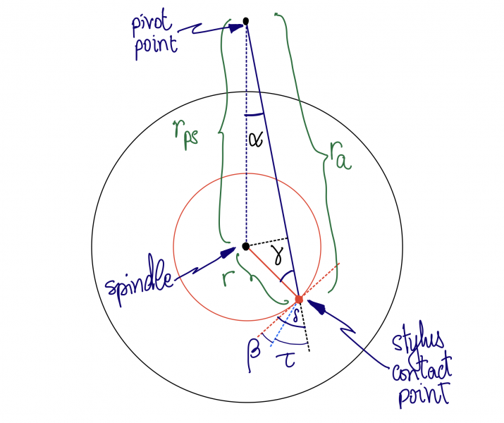
Screenshot 2023-09-08 at 09.21.27.png


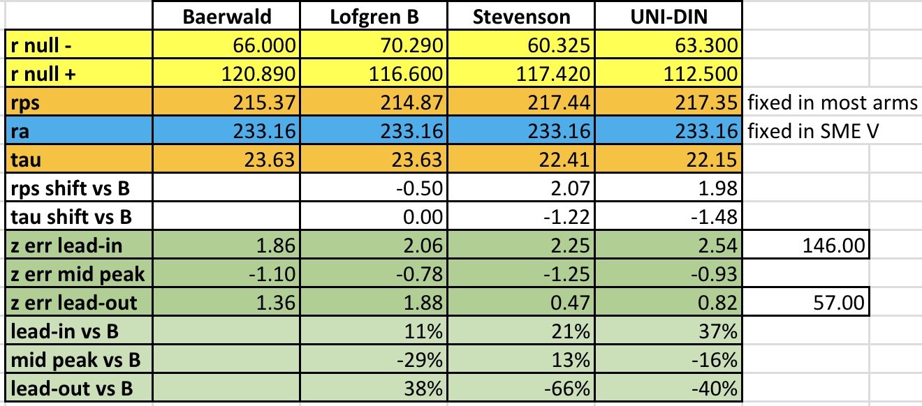
After doing the math (link below with full details) you get that:
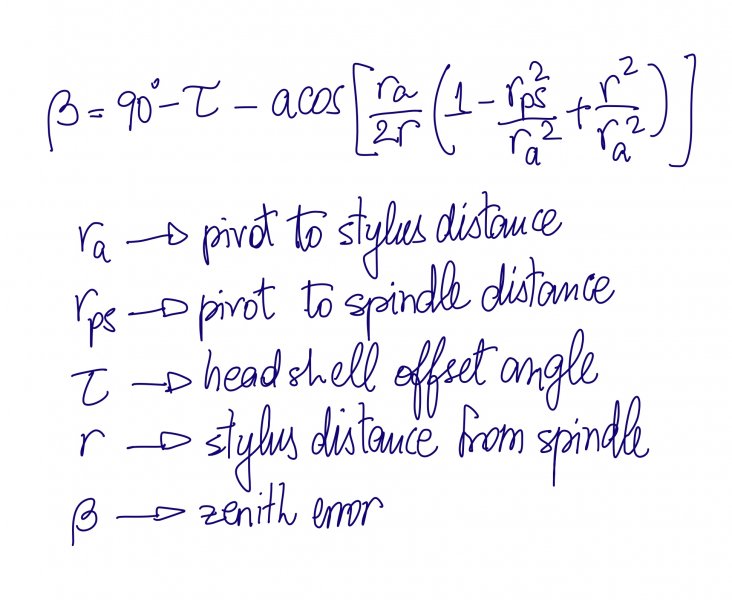
Screenshot 2023-09-08 at 09.24.13.jpeg

Full derivation and more details at: https://bit.ly/zenith-math

What is interesting here is that:
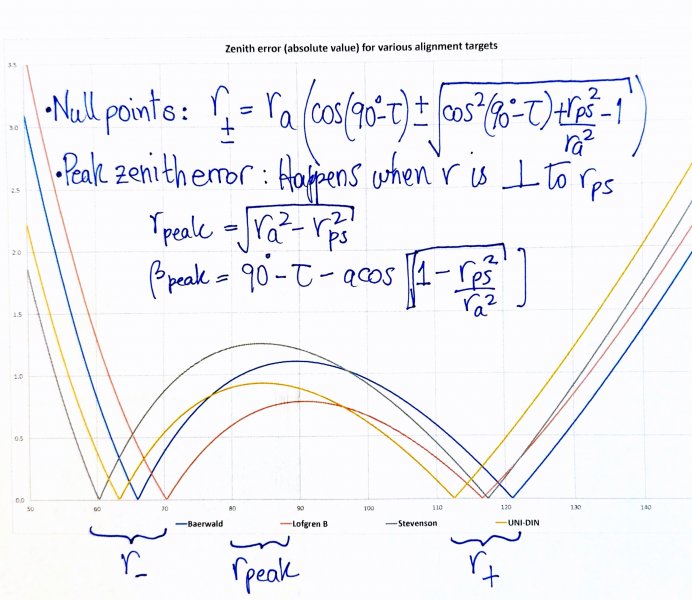
1- Given two null points (r+ and r-, in any of the conventions) determines the relationship between rps and ra as:

ra^2 - rps^2 = r+ * r-

Which means you can adjust ra (or rps in the SME V) to accomodate any convention

2- Similarly, given the null points r+, r-, and ra, the offset angle is:

tau = 90 - acos( (r+ + r-) / (2*ra) )

And what this means is:
A- Choice of null points determines ra vs rps
B- Once we get ra and rps right, aligning the null points is always possible

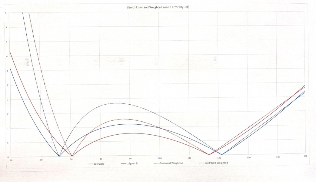
A plot of abs(beta) function for various alignment conventions:
IMG_3819.jpeg

miguelito
 
Last edited:

mtemur

Well-Known Member
Mar 26, 2019
1,413
1,362
245
48
Thank you @miglto for doing the math and sharing with us. FYI instead of the terms Zenith Error" and "Pivot To Stylus" tracking error and effective length are widely used. Additionally all geometries are based on reducing distortion which increases closer to label. Distortion figures are a function of tracking error and groove radius.

More importantly the calculations you shared are based on IEC standard for inner and outer groove radiuses. When inner and outer groove radiuses change the null points change too. Baerwald (Lofgren A) aims to equalize distortion at inner groove, outer groove and the peak between null points. Lofgren B aims to lower peak distortion between null points and Stevenson aims to lower distortion closer to inner groove. There isn't too much information about UNI-DIN.

You can access all of this and more at vinyl engine.
 

miglto

Active Member
Oct 17, 2021
32
34
25
NYC
instagram.com
Thank you @miglto for doing the math and sharing with us. FYI instead of the terms Zenith Error" and "Pivot To Stylus" tracking error and effective length are widely used. Additionally all geometries are based on reducing distortion which increases closer to label. Distortion figures are a function of tracking error and groove radius.
Got it. I hope the diagram makes it clear what I am talking about. As for distortion, I have looked at a simple model of that and what I find is that distortion from zenith error (I will keep using this term because there’s also azimuth error) is proportional to the frequency and inversely proportional to the radius. So if you take 146mm as a reference point (you can take whatever reference point) then the IMD plot comparing Baerwald and LofgrenB would be the dashed lines here:

IMG_3878.jpeg

More importantly the calculations you shared are based on IEC standard for inner and outer groove radiuses. When inner and outer groove radiuses change the null points change too. Baerwald (Lofgren A) aims to equalize distortion at inner groove, outer groove and the peak between null points. Lofgren B aims to lower peak distortion between null points and Stevenson aims to lower distortion closer to inner groove. There isn't too much information about UNI-DIN.

You can access all of this and more at vinyl engine.
The calcs are pure geometry, the null points don’t change - please see the derivations, there is no assumption at all other than geometry.

You might be referring to my table on the second post where I put in some number for ra or rps - this is just an example from my SME V tonearm. The equations above do not depend at all on any of that - for example will apply the same to any tonearm length be it 9”, 12” or 30”.

I will also clarify that the null point positions are the “official” positions for Baerwald, LofgrenB, Stevenson, and UNI-DIN. But in fact you could come up with your own null points, use that to determine either ra or rps from the fomula above (whichever you can change), and create an appropriate template for alignment with grids at the null points of your choosing.

Thx.

miguelito
 
Last edited:

Kjetil

Well-Known Member
Oct 28, 2022
200
264
70
58
Hamar, Norway

mtemur

Well-Known Member
Mar 26, 2019
1,413
1,362
245
48
I hope the diagram makes it clear what I am talking about. As for distortion, I have looked at a simple model of that and what I find is that distortion from zenith error (I will keep using this term because there’s also azimuth error) is proportional to the frequency and inversely proportional to the radius.
Those geometries are dealing cartridge alignment on horizontal plane that's why only tracking error and tracking distortion are the case here. Azimuth is another issue and not related with these geometries.

The calcs are pure geometry, the null points don’t change - please see the derivations, there is no assumption at all other than geometry.
Null points do change depending standard about inner and outer groove radiuses.

You might be referring to my table on the second post where I put in some number for ra or rps -
I'm referring both to your table and graph because both indicate groove radiuses.

this is just an example from my SME V tonearm. The equations above do not depend at all on any of that - for example will apply the same to any tonearm length be it 9”, 12” or 30”.
Of course null points don't change according to tonearm length. Null points are determined by geometry and inner and outer groove radiuses.

I will also clarify that the null point positions are the “official” positions for Baerwald, LofgrenB, Stevenson, and UNI-DIN. But in fact you could come up with your own null points, use that to determine either ra or rps from the fomula above (whichever you can change), and create an appropriate template for alignment with grids at the null points of your choosing.
Those are "official" null points only for IEC standard. There are other null points for other standards (DIN, JIS) or you can decide new inner and outer groove radiuses depending on your record collection which will dictate new null points. BTW are those UNI-DIN null points officially shared by Acoustical Systems? Because AS is the inventor of UNI-DIN.

I hope those will help to clarify things.
 

miglto

Active Member
Oct 17, 2021
32
34
25
NYC
instagram.com
Null points do change depending standard about inner and outer groove radiuses.

I'm referring both to your table and graph because both indicate groove radiuses.

Of course null points don't change according to tonearm length. Null points are determined by geometry and inner and outer groove radiuses.
I don’t think this is right. The null points are:

IMG_3989.jpeg

And this is literally just geometry that does not depend at all on inner or outter radii.
 
  • Like
Reactions: Another Johnson

miglto

Active Member
Oct 17, 2021
32
34
25
NYC
instagram.com
BTW are those UNI-DIN null points officially shared by Acoustical Systems? Because AS is the inventor of UNI-DIN.
Yes these should be the official UNI-DIN null point locations. But using the formulas and a spreadsheet you can recalculate anything you want.

The table in my second post only takes the null points and ra (in this case, you can change it to rps) as input.
 
  • Like
Reactions: Another Johnson

mtemur

Well-Known Member
Mar 26, 2019
1,413
1,362
245
48
Desr @miglto I suggest you investigate the subject more thoroughly. After that we will discuss it again.
 

mtemur

Well-Known Member
Mar 26, 2019
1,413
1,362
245
48
Check the math I posted. It is very straightforward. Please let me know if you find a mistake. Thx.
Yes, there is something fundamentally wrong with your math because you can not use the same formula for all geometries. There are fundamental differences between geometries about handling distortion. Their approach and groove radiuses define null points. It is not like that there are pre determined null points for each geometry and all use the same approach and same formula.

Take my advice and read more about this subject before reaching to a conclusion. Try investigating;
- Why there are different null points for different geometries?
- What is the approach of each geometry to handle distortion?
- Who decide those null points and why?
 

miglto

Active Member
Oct 17, 2021
32
34
25
NYC
instagram.com
Yes, there is something fundamentally wrong with your math because you can not use the same formula for all geometries. There are fundamental differences between geometries about handling distortion. Their approach and groove radiuses define null points. It is not like that there are pre determined null points for each geometry and all use the same approach and same formula.

Take my advice and read more about this subject before reaching to a conclusion. Try investigating;
- Why there are different null points for different geometries?
- What is the approach of each geometry to handle distortion?
- Who decide those null points and why?
Yes you can. It is geometry. It is calculating angles. For the record, I know math (I have a PhD in Physics). If you can point what is wrong with the math - specifically - I will take a look. But you’re not giving me any factual argument.

Null points and where to put them is rather arbitrary. Case in point: If you care for less distortion (ie zenith error) at the end of the record, then choose Stevenson. If you care for lowest distortion in the middle, then LofgrenB. If you want to come up with your own two null points, you can.
 
Last edited:
  • Like
Reactions: Another Johnson

miglto

Active Member
Oct 17, 2021
32
34
25
NYC
instagram.com
Additionally your comments on that table "fixed in most arms" for P2S distance and "fixed in SME V" for effective length are wrong as well as figures.
It is correct. In most arms the headshell has slots, and the p2s is fixed by whatever you drilled on the armboard. In the SME V the pivot moves, and the headshell has two M2.5 sized holes so no adjustability on the headshell. That is what those comments mean.

As you can verify in the math, there’s a relationship between the null points, ra and rps. Fix the null points and rps and you find out what ra is, for example.
 

mtemur

Well-Known Member
Mar 26, 2019
1,413
1,362
245
48
For the record, I know math (I have a PhD in Physics). If you can point what is wrong with the math - specifically - I will take a look. But you’re not giving me any factual argument.
For the record I studied naval architecture/naval engineering and I took a totally different job but I know one or two things about this vinyl stuff. I'm happy to hear that you have a PhD in Physics. This should be much easier for you then.

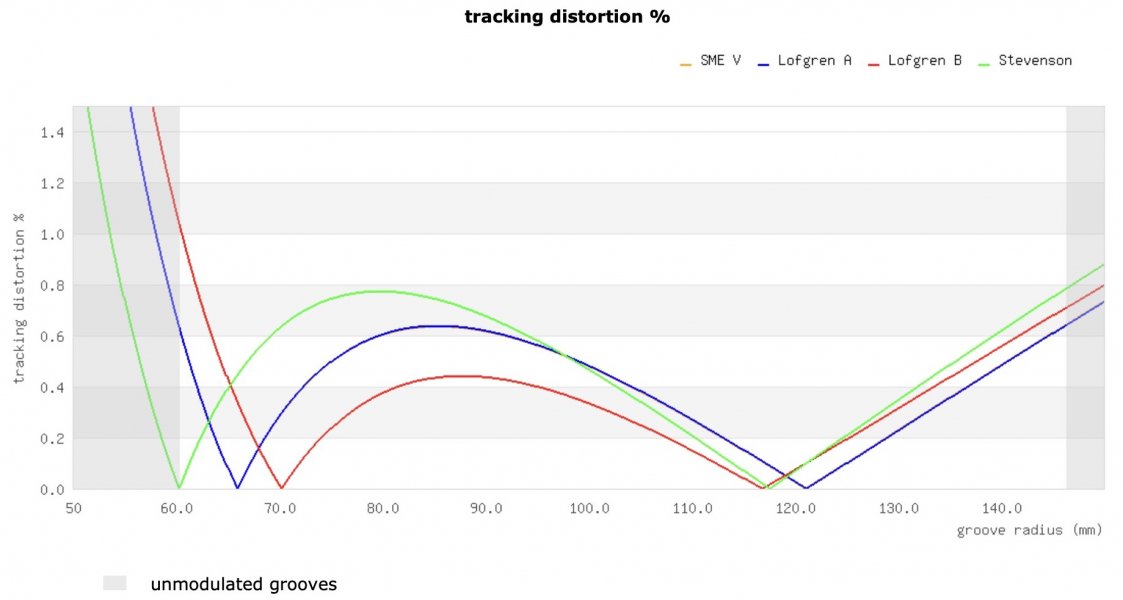
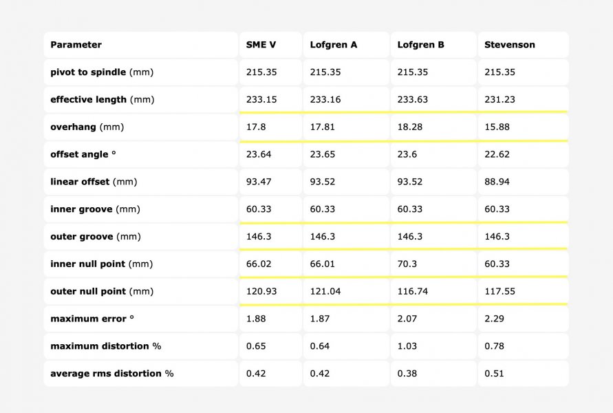
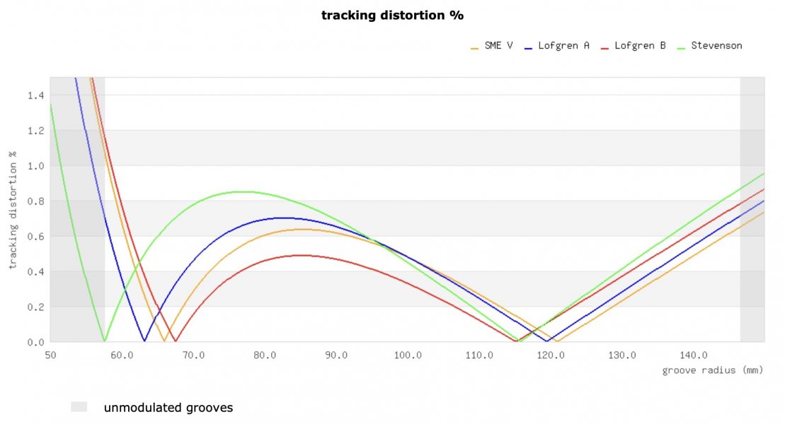
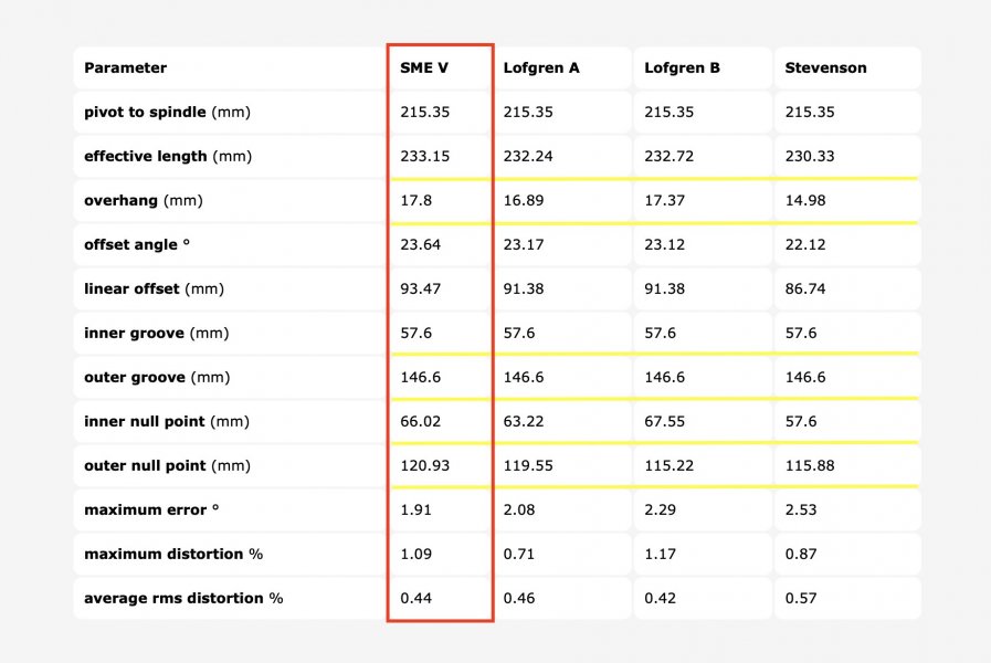
I own a SME V since 2008 and very well know that tonearm. Here is the correct graph and table for SME V. It is based on IEC standard (146.3mm and 60.325mm). Yellow line is for SME V but it is behind Blue Lofgren A. Please check the table especially inner and outer groove radiuses. You can also notice the change in overhang.

Ekran Resmi 2023-09-20 21.55.01.jpg
Ekran Resmi 2023-09-20 21.54.57.jpg


Here is the same graph but inner and outer groove radiuses changed to JIS standard (146.6mm and 57.6mm) while SME V kept the same (IEC). You can clearly see how everything is changed.
Ekran Resmi 2023-09-20 21.59.21.jpg
Ekran Resmi 2023-09-20 21.59.13.jpg

The inescapable conclusion is:
- SME V is based on Lofgren A IEC
- When standard is changed null points also change.

You can start investigating here.
 
Last edited:

mtemur

Well-Known Member
Mar 26, 2019
1,413
1,362
245
48
It is correct. In most arms the headshell has slots, and the p2s is fixed by whatever you drilled on the armboard. In the SME V the pivot moves, and the headshell has two M2.5 sized holes so no adjustability on the headshell. That is what those comments mean.
You totally misunderstood the concept of SME V or any sliding base tonearm. The idea behind sliding base tonearms (SME) is depending on the distance between cartridge's fixing holes center to stylus tip altering effective length and pivot to spindle (P2S) distance in order to keep overhang constant. When cartridge's fixing holes center to stylus tip is 9.52mm you can achieve 215.35mm P2S distance and 233.15mm effective length listed in specs. Otherwise those figures slightly change. BTW it is only possible with Lyra cartridges.
 

miglto

Active Member
Oct 17, 2021
32
34
25
NYC
instagram.com
For the record I studied naval architecture/naval engineering and I took a totally different job but I know one or two things about this vinyl stuff. I'm happy to hear that you have a PhD in Physics. This should be much easier for you then.

I own a SME V since 2008 and very well know that tonearm. Here is the correct graph and table for SME V. It is based on IEC standard (146.3mm and 60.325mm). Yellow line is for SME V but it is behind Blue Lofgren A. Please check the table especially inner and outer groove radiuses. You can also notice the change in overhang.

View attachment 116883
View attachment 116882


Here is the same graph but inner and outer groove radiuses changed to JIS standard (146.6mm and 57.6mm) while SME V kept the same (IEC). You can clearly see how everything is changed.
View attachment 116884
View attachment 116885

The inescapable conclusion is:
- SME V is based on Lofgren A IEC
- When standard is changed null points also change.

You can start investigating here.
If you plug ra, rps, and tau in the formulas I posted you will recover the null points. What null points are used is an arbitrary choice based on preference. Notice you DON’T need inner or outter radii or anything else.

To be clear:
ra —> “effective length”
rps —> “pivot to spindle”
tau —> “offset angle”
 
Last edited:
  • Like
Reactions: Another Johnson

mtemur

Well-Known Member
Mar 26, 2019
1,413
1,362
245
48
What null points are used is an arbitrary choice based on preference.
No, they are not chosen arbitrarily when it comes to Lofgren A, B, Stevenson or UNI-DIN. Those null points are chosen in order to reach design goals of each geometry over the recorded area of vinyl record. The limits of the recorded area is determined by the standard (IEC, DIN, JIS) which inevitably changes null points.

Everybody agrees on this but you don't. It is unbelievable to see you still arguing. Please do some research.
 

About us

  • What’s Best Forum is THE forum for high end audio, product reviews, advice and sharing experiences on the best of everything else. This is THE place where audiophiles and audio companies discuss vintage, contemporary and new audio products, music servers, music streamers, computer audio, digital-to-analog converters, turntables, phono stages, cartridges, reel-to-reel tape machines, speakers, headphones and tube and solid-state amplification. Founded in 2010 What’s Best Forum invites intelligent and courteous people of all interests and backgrounds to describe and discuss the best of everything. From beginners to life-long hobbyists to industry professionals, we enjoy learning about new things and meeting new people, and participating in spirited debates.

Quick Navigation

User Menu

Steve Williams
Site Founder | Site Owner | Administrator
Ron Resnick
Site Co-Owner | Administrator
Julian (The Fixer)
Website Build | Marketing Managersing