


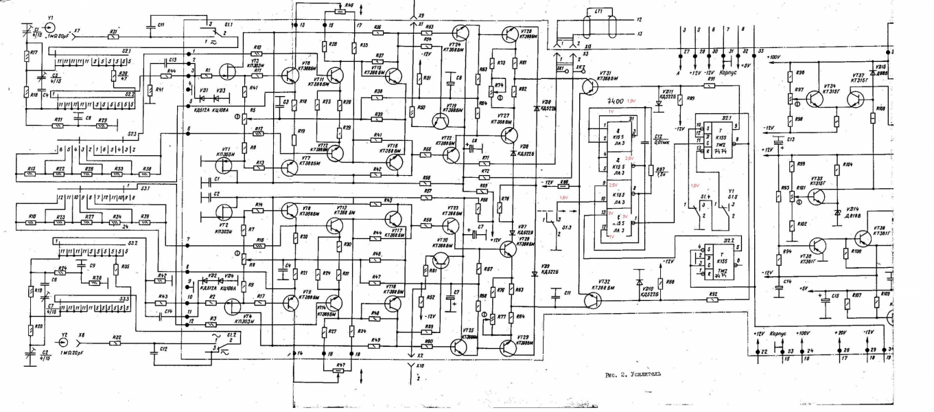
I'm an electronical enthusiast and I have an URSS oscilloscope that it's broken.
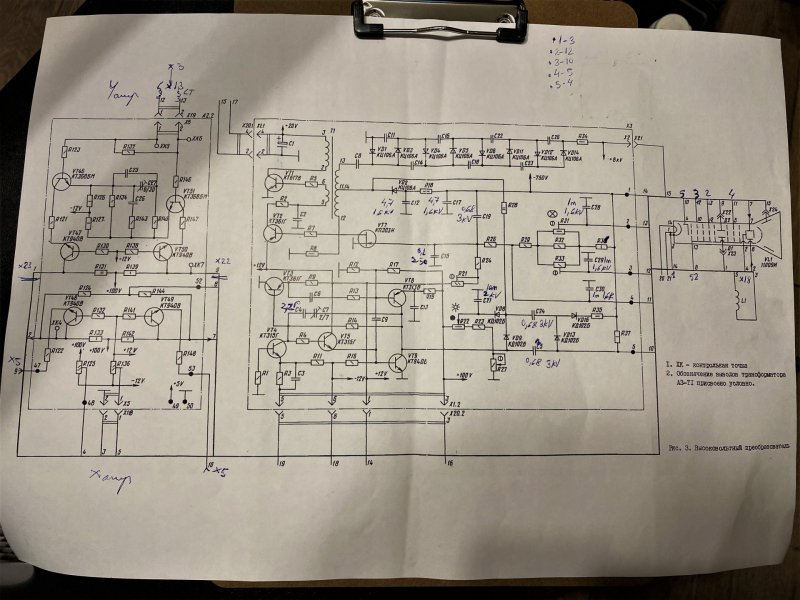
the main problem it's in the high voltage power supply,
another problem it's my lack of knowledge about CRT and how they work.
I found the data sheet for this CRT valve but I can't understand what it's the pin no. 2 on and what this is doing.
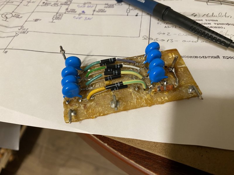
first I try to repair the original power supply which is made with an iron powder transformer and self-oscilation circuit but this doesn't work properly and I couldn't make this supply to work properly.
now i try to make another type of power supply that it's based on push-pull topology and another core ( ETD34 ) at 30kHz. unfortunately I didn't had time to experimented with this new supply.
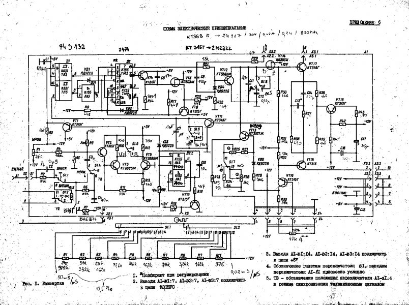
Now I want to understand what does every plate in this tube and I want to check all the supply voltages without the tube connected to be sure that everything it's fine.
I know that on:
pin 1 and 14 it's the heater lamp (also this it's checked and it seems to be ok )
pin 2 it's a mistery (this pin it's connected via an potentiometer between -12V and +100Vcc), maybe with this pot can I adjust some geometrical issues?
pin 3 it's the cathode
pin 4 it's the gride
pin 5 it's the 4th anode
pin 6,9,11 not used
pin 7,8 X (time base ) plates
pin 10 astigmatism
pin 12 focus
pin 13 2nd anode accelerating
D1,D2 Y plates
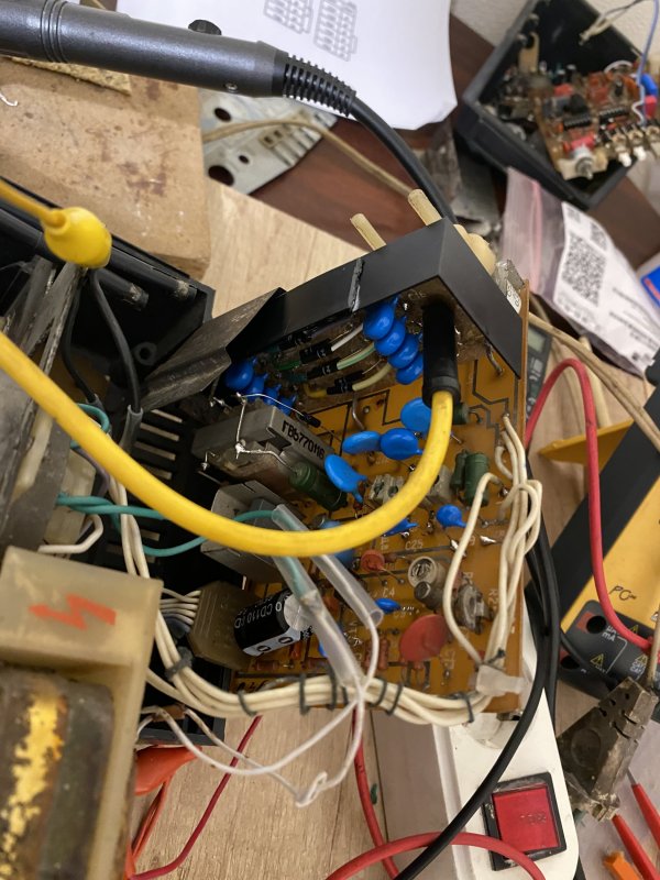
For more photos I leave below links:


the main problem it's in the high voltage power supply,
another problem it's my lack of knowledge about CRT and how they work.
I found the data sheet for this CRT valve but I can't understand what it's the pin no. 2 on and what this is doing.
first I try to repair the original power supply which is made with an iron powder transformer and self-oscilation circuit but this doesn't work properly and I couldn't make this supply to work properly.
now i try to make another type of power supply that it's based on push-pull topology and another core ( ETD34 ) at 30kHz. unfortunately I didn't had time to experimented with this new supply.
Now I want to understand what does every plate in this tube and I want to check all the supply voltages without the tube connected to be sure that everything it's fine.
I know that on:
pin 1 and 14 it's the heater lamp (also this it's checked and it seems to be ok )
pin 2 it's a mistery (this pin it's connected via an potentiometer between -12V and +100Vcc), maybe with this pot can I adjust some geometrical issues?
pin 3 it's the cathode
pin 4 it's the gride
pin 5 it's the 4th anode
pin 6,9,11 not used
pin 7,8 X (time base ) plates
pin 10 astigmatism
pin 12 focus
pin 13 2nd anode accelerating
D1,D2 Y plates
11LO9I (11ЛО9И) Oscilloscope CRT
lampes-et-tubes.info
For more photos I leave below links:
Attachments
-
 A274CC03-F883-4CC2-BFA2-990DE6D768D4.thumb.jpeg.7aeeaaa084f33d1b036cea906ba72f1c.jpeg377.2 KB · Views: 0
 -
 CTR sch.jpeg448.7 KB · Views: 0
 -
 D2C9B6CB-6555-4A8C-92AF-62D4CB709CFA.thumb.jpeg.cc4a5309eb0e9495a8aecbaa9502789e.jpeg358.3 KB · Views: 0
 -
 0FFE10A3-9296-4A1D-ABAB-0C82FD32DF49.jpeg709.2 KB · Views: 0
 -
 28725C7D-0A42-44C5-8366-A2F0257ED859.png2 MB · Views: 0
 -
 D0A0C9D9-4DF5-4434-9330-C4193DB9E51F.jpeg676.3 KB · Views: 0