Noise. That damned demon you may not even know about...

no need to measure leakage current or chassis voltage when we can listen to music in both ac polarity (proper and inverted) and choose which sounds better
maybe, but it's about noise&hum (grounding loops). I mainly want to improve that If you don't want that, that's fine. I want to get the best out of what I can.
My tip read a book about it
 
  • Like
Reactions: Amir and dennis h
I did a dive on measuring noise. To get into the giga hertz where RF lies, you need a spectrograph. Problem is, to connect rhe spectragraph to a cable, you need an interface. Those interface only work at low megahertz. The way to measure gigahertz would require an antenna. But that antenna will read all the noise in the room. So you need a faraday cage to seal it. But a hole the size of a power cord is a big leak. So you will still read the outsode environment.
 
Here's a thought. Rf noise will only travel a couple hundred feet on a power line before it dissipates. The fancy filter that says it's removing RF, for one, how did they measure it, and two, it has all coupled back to the power cord and chassis after the filter. So, whats it doing for you as far as noise from cell phones.
 
I did a dive on measuring noise. To get into the giga hertz where RF lies, you need a spectrograph. Problem is, to connect rhe spectragraph to a cable, you need an interface. Those interface only work at low megahertz. The way to measure gigahertz would require an antenna. But that antenna will read all the noise in the room. So you need a faraday cage to seal it. But a hole the size of a power cord is a big leak. So you will still read the outsode environment.
RF or radio frequency is defined as the electromagnetic spectrum between 3KHz and 300 GHz. Any signal in that spectrum can interfere with electronics. The lower frequency has longer wavelength; higher frequency has shorter wavelength. These signals going through electronics can interact and result in noise. Good designers will consider this in their grounding layout. component separation, component selection and noise decoupling techniques. Case design and chassis ground will help reduce susceptibility. Screens for cooling air flow can also be selected to allow air flow and reduce RF. Not all RF is going to be a problem or result in a degradation of the sound. It really all depends on a number of factors.

These days there are numerous sources since people have cell phones and all sorts of electronic devices. The proliferation of cell towers and blanketing areas with wifi, 4G and 5G fields are other sources.
 
  • Like
Reactions: wil
Here's a thought. Rf noise will only travel a couple hundred feet on a power line before it dissipates. The fancy filter that says it's removing RF, for one, how did they measure it, and two, it has all coupled back to the power cord and chassis after the filter. So, whats it doing for you as far as noise from cell phones.
RF noise impinging on a power line will affect the entire line equally once the RF is of sufficiently high frequency and the source is far enough away. A cell phone next to a power cord is one thing, but a cell tower, radio or TV transmitter will hit the power lines equally once you are more than a a block or so away.

Power line filters are mostly for conducted radiation - the noise travelling on the conductors in the power line. Airborne fields or radiated emissions are addressed differently. Alas, some of it is more guess and trial/error with commonly used methods.
 
I did a dive on measuring noise. To get into the giga hertz where RF lies, you need a spectrograph. Problem is, to connect rhe spectragraph to a cable, you need an interface. Those interface only work at low megahertz. The way to measure gigahertz would require an antenna. But that antenna will read all the noise in the room. So you need a faraday cage to seal it. But a hole the size of a power cord is a big leak. So you will still read the outsode environment.
Here's a thought. Rf noise will only travel a couple hundred feet on a power line before it dissipates. The fancy filter that says it's removing RF, for one, how did they measure it, and two, it has all coupled back to the power cord and chassis after the filter. So, whats it doing for you as far as noise from cell phones.

We can find this information on the pages of the manufacturers and associated links. https://www.whatsbestforum.com/thre...ou-may-not-even-know-about.40543/post-1089706

But what is the point of getting great measurements if we do not know what to look for? As often referred the RF spectra is extremely high and we do not know what specific bands must be exactly addressed when dealing with interference introduced by the mains supply. Unless the comments are quantified in Hz everyone is surely an expert ...

Just for fun, not a systematic study, long ago I tried injecting RF noise in my mains supply feeding my system using a Hewlet Packard RF noise generator, but could not affect its sound quality. But my system was properly grounded, with adequate layout.
 
  • Like
Reactions: wil
RF noise impinging on a power line will affect the entire line equally once the RF is of sufficiently high frequency and the source is far enough away. A cell phone next to a power cord is one thing, but a cell tower, radio or TV transmitter will hit the power lines equally once you are more than a a block or so away.

Power line filters are mostly for conducted radiation - the noise travelling on the conductors in the power line. Airborne fields or radiated emissions are addressed differently. Alas, some of it is more guess and trial/error with commonly used methods.
Do you have a background in radio and such? I am trying to learn more. Especially about how to measure noise. Noise that is more in the 20K and 100K range. With the associated harmonics.

I get the RF has a very broad band. And it impinges large section. My point was that it does dissipate quick. So if your not near an issue, it won't travel miles and find you. On the flip side, if you are being hit, a filter may clean up what is before it, but its not doing anything for what comes after it. And its easy for it to couple back into a cord or a chassis. Makes me wonder about shielded cables.
 
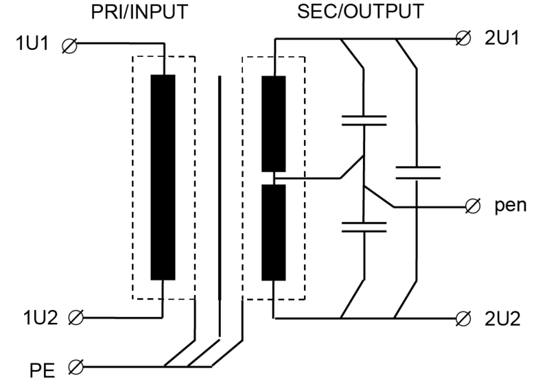
Buy a high-quality interference suppression transformer to eliminate 95% of all high-frequency problems. highly effective from 5khz to gigahertz.csm_EMV-Stoerschutz-Transformer_d452461971.png

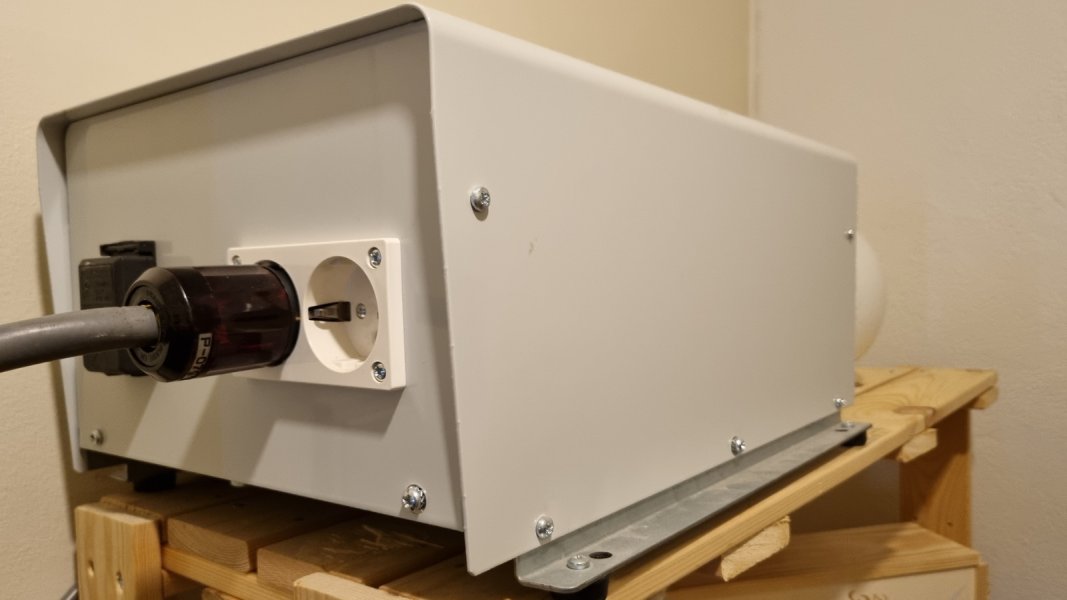
Noratel have the best performance 5kva ~ 55kg heavy beast
against the last 5% of interference radiation into your room. e.g. dect telephone etc. only a well-shielded housing and grounding helps.
 
Last edited:
Buy a high-quality interference suppression transformer to eliminate 95% of all high-frequency problems. highly effective from 5khz to gigahertz.View attachment 161591

Noratel have the best performance 5kva ~ 55kg heavy beast
against the last 5% of interference radiation into your room. e.g. dect telephone etc. only a well-shielded housing and grounding helps.

Unfortunately the Achile's heel of such screening systems - used in medical transformers for safety reasons - is the quality of the earth point. Typically ground resistance is a resistive value measured with a 50 or 60 Hz signal - as frequency increases the impedance increases.

The problem is much more complex than we can figure - it is why people write long and exhaustive excellent books on the subject, such as
https://www.amazon.co.uk/Grounding-...p-111918374X/dp/111918374X/ref=dp_ob_title_bk

The link refers to the 2016 edition - due to the evolution of electronics devices, such as computers and mobile systems , the edition a few of us studied is now obsolete ...

Most high-end designers did not read the book, so their products have non- predictable performance in terms of RF interference. An ideal device would be insensitive to mains quality and RF interference. Knowing that there are no ideal devices, laboratories, military, studios and manufacturing facilities have strict rules to deal with it. But in the non ruled high-end forest where anything grows all we have is a mix of empirical knowledge, fortunately some times complemented with science.
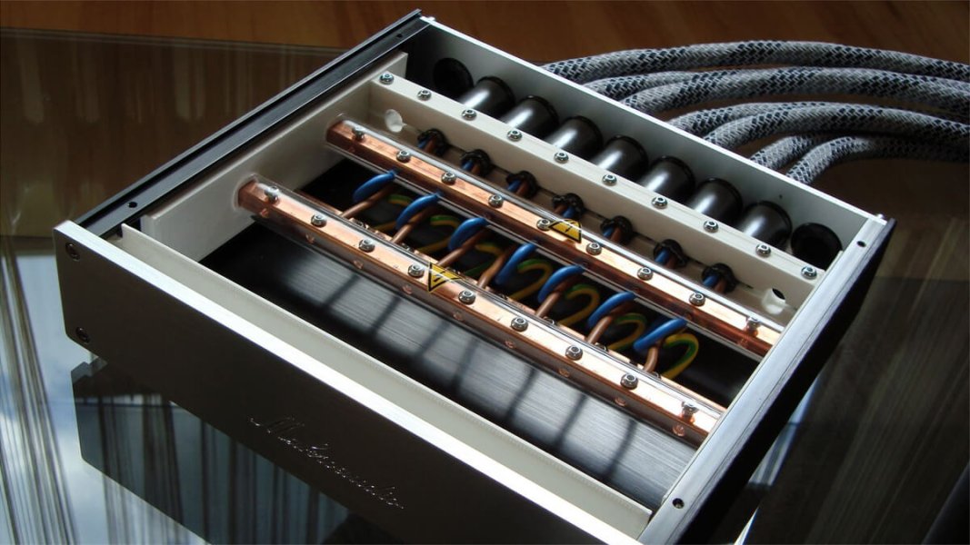
I use the noratel transformer and star grounding powerbar that solution works pretty fine.
Of course, there are certainly better solutions in the world. What was important to me was that there were no restrictions when it came to dynamic in music. This is usually the main problem with such solutions.
873_de1748f9-a148-4e08-bdb6-a717e54d2d0a.jpg


makroaudio-stromverteiler-mk2-0321.jpg0636736847_0_g.jpg
P. S I linked that book too at post #261
 
Last edited:
  • Like
Reactions: engadin
An ideal device would be insensitive to mains quality and RF interference.


I think poor ac power destroy everything and there is no way to design insensitive audio systems

Audio manufactures should design a high current 30kva battery inverter completely isolated from home ac power
 
Rf is also is not a simple problem. Some believes even many RLC filter stages can not 100% stop RF so some companies like lessloss use no cap or coils.
 
I use the noratel transformer and star grounding powerbar that solution works pretty fine.
Of course, there are certainly better solutions in the world. What was important to me was that there were no restrictions when it came to dynamic in music. This is usually the main problem with such solutions.


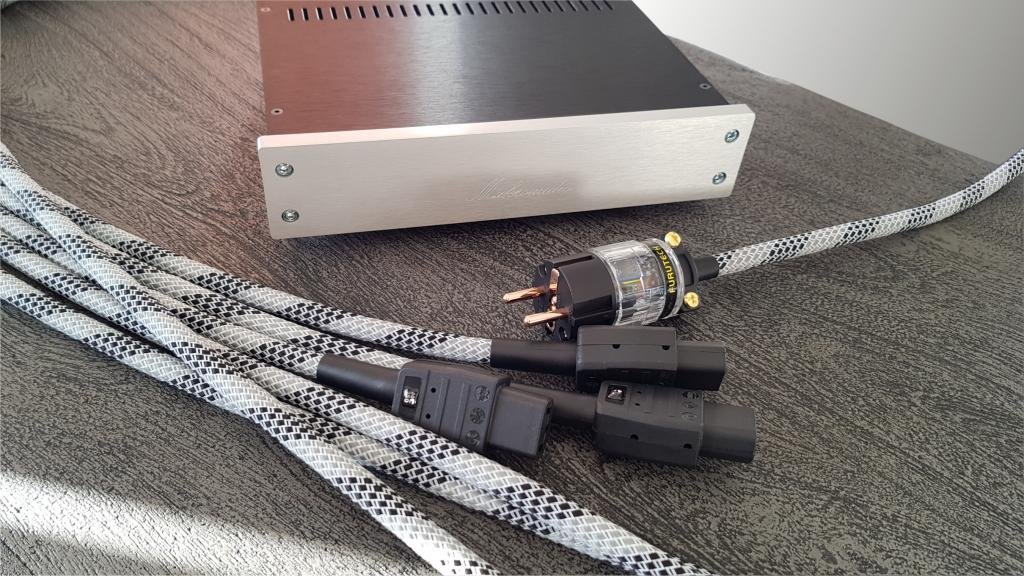
View attachment 161598View attachment 161599
P. S I linked that book too at post #261
Is that a power distribution box with captured male ends. I like it. I built similar. its the best distribution I have hear in my system. So much better to get rid of duplex.
 
  • Like
Reactions: DasguteOhr
I think poor ac power destroy everything and there is no way to design insensitive audio systems

Audio manufactures should design a high current 30kva battery inverter completely isolated from home ac power
Not that hard to do, but about $30K to $50K in parts alone to make. Buy a Tesla Powerwall and use the load end to feed a 10KVA isolation transformer by Torus. Or get a larger Controlled Power unit.
 
I think poor ac power destroy everything and there is no way to design insensitive audio systems

Again, if you specify and quantify your claims they can have some meaning. Otherwise they rank with Armageddon claims.

Audio manufactures should design a high current 30kva battery inverter completely isolated from home ac power

Why not 100 kVA? Even applying a logarithmic factor considering the law of diminishing returns it will probably sound around two times better. ;)
 
I think poor ac power destroy everything and there is no way to design insensitive audio systems

Audio manufactures should design a high current 30kva battery inverter completely isolated from home ac power.
How many watts does your audio system require?
 
Do you have a background in radio and such?
Yes, electrical engineering.
I have not worked on the design side for a long time. My work is concerned with regulatory compliance and some aspects of design assurance. That includes environmental testing. An aspect of that testing is radiated and conducted emissions and susceptibility, high intensity radio frequency (HIRF), lightning, etc. My keen interest and specialty is software assurance and design assurance for complex electronic hardware such as FPGA, ASIC, CPLD and complex COTS devices.
In the past I did work on a design for FCC compliance. Also worked early in my career for a radio company (Harris).

Especially about how to measure noise. Noise that is more in the 20K and 100K range. With the associated harmonics.
That's a different beast than RF/EMI in the MHz up range.
There are commercial products that measure noise and distortion in audio signals.
The next question is - then what? The designer "should" use best practices and methods for component selection, circuit card layout, separation and segregation of analog and digital domains, grounding schemes, power architecture and distribution. Any digital circuit for audio will generate noise in the spectrum cited. The trick is to minimize it and minimize its effect on the other circuits, especially preventing coupling into the analog side.
I get the RF has a very broad band. And it impinges large section. My point was that it does dissipate quick. So if your not near an issue, it won't travel miles and find you. On the flip side, if you are being hit, a filter may clean up what is before it, but its not doing anything for what comes after it. And its easy for it to couple back into a cord or a chassis. Makes me wonder about shielded cables.
Audio electronics are nearly transparent at the wavelength of those GHz frequencies. From a tower or transmitter, the energy radiates spherically (or along its tuned dispersion). If you are next to a device such as a WiFi router or cell phone, then there would be some coupling and injection into power cables, connectors and through an unshielded or ungrounded chassis. A chassis ground does help protect against radiated EMI.
 
How many watts does your audio system require?
Bingo!
I have some rather large Class A SET amps. Just in those monoblocks I need 800 watts. Add another 600 watts when I biamp. The phono stage is all tube and uses 700 watts. That's 2100 watts! Not sure I want that kind of battery and invertor in the listening room. Invertors are noisy.
 

About us

  • What’s Best Forum is THE forum for high end audio, product reviews, advice and sharing experiences on the best of everything else. This is THE place where audiophiles and audio companies discuss vintage, contemporary and new audio products, music servers, music streamers, computer audio, digital-to-analog converters, turntables, phono stages, cartridges, reel-to-reel tape machines, speakers, headphones and tube and solid-state amplification. Founded in 2010 What’s Best Forum invites intelligent and courteous people of all interests and backgrounds to describe and discuss the best of everything. From beginners to life-long hobbyists to industry professionals, we enjoy learning about new things and meeting new people, and participating in spirited debates.

Quick Navigation

User Menu

Steve Williams
Site Founder | Site Owner | Administrator
Ron Resnick
Site Owner | Administrator
Julian (The Fixer)
Website Build | Marketing Managersing