FFT audio analysis flaws?

DonH50

Member Sponsor & WBF Technical Expert
Jun 22, 2010
3,964
323
1,670
Monument, CO
Just Don (H = Herman, 50 = age I joined this wondrous forum).

Sorry, I was thinking of the masking effects of tones located close to a much larger signal. While close-in phase noise could also be masked, I am not sure its audibility, meaning I have not personally run a controlled test. Off the cuff, I would think by making the signals wander it could certainly introduce an annoying warble or beat to the sound. Have to be pretty large, though, at least IMO. The busier the signal, the less likely we'd be to notice, of course. But, it may be one of the many things noticeable by its absence. 0.1 Hz is 10-second pattern and I too find it very hard to believe such a long period would be noticeable.

I have no idea if the IQ test measures Allan variance, or even how important that would be. I need to read up more on the test but that will have to wait for the weekend.

We should ping Kal as I think he (and others, I am sure) have much deeper knowledge of psychoacoustics. Me, I am a simple country boy, a hairy-knuckled engineer, not a high-brow real science type. :) This is mostly over my head, I am trying to stick to what little I know of the actual circuits and such.
 

jkeny

Industry Expert, Member Sponsor
Feb 9, 2012
3,374
42
383
Ireland
OK, Don it is.
I'm not sure the original appearance of these graphs but they appear to come from Paul Miller over at Hi-Fi news

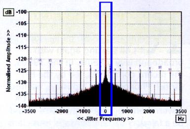
First one shows a standard jitter spec as normally published & seen - nothing unusual
Standard.jpg

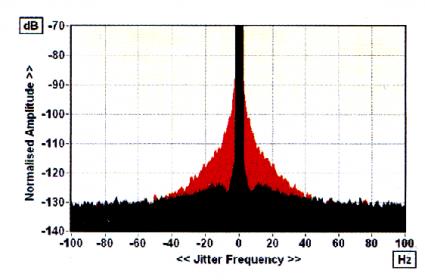
Second one shows the same plot zoomed in & here we can see the red area is the close-in phase noise which just shows a s a wider base on normal view but here you can see that, right in against the central spur, it ranges all the way up to -70 maybe even -60dB
100xStandard.jpg

As I said, I'm still trying to get my head around these issues & how significant they are/aren't.
Would even more magnification show some close-in jitter going all the way close to 0dB?
Would this be audible? In what way audible? Are we getting close to the wow & flutter in analogue systems where Amir said that even though close to the fundamental frequency & masking would be expected, it was the strength of the wow & flutter signal that caused it to be audible as amplitude modulation.
 

DonH50

Member Sponsor & WBF Technical Expert
Jun 22, 2010
3,964
323
1,670
Monument, CO
I strongly suspect that is inaudible.

Theoretically an ideal noise source can go to infinity right at the carrier frequency (0 Hz offset). There are, ahem, practical limits, and in any event once it gets so close to the signal there is no way to distinguish it from the signal itself (technically it still modulates the signal, but it is undetectable).

This may be a different issue that the rapid changes in rate shown in the previous pages. Windowing tends to weight out such small discontinuities but they could still be audible. That said, when talking 1 ppm on the sampling clock we are talking only ~20 ps and only briefly. Again, I strongly suspect there are many other things that would swamp this effect. Differences in digital/analog filter and analog output buffer stages, for example.

Looked at another way, 1% distortion is the accepted threshold of audible distortion, or -40 dB relative to the signal. Also, 0.1% distortion is deemed inaudible by many, and that is -60 dB (voltage). So, -90 dB is 0.003162 % -- is that audible?

I would expect phase noise, to the extent it is random, to be less audible than the periodic wow and flutter tapes and records produce just because it is random.

I am still tempted to build a test case to show what it sounds like, but of course it would have to be large enough (noise high enough) to hear what it sounds like. If I built a test with -80 dB or better, which is probably as good or worse than the majority of playback system DACs, we couldn't tell if it was the test signal or added by the system. Assuming we could hear it at all.

All IMO - Don
 

amirm

Banned
Apr 2, 2010
15,813
38
0
Seattle, WA
Looked at another way, 1% distortion is the accepted threshold of audible distortion, or -40 dB relative to the signal. Also, 0.1% distortion is deemed inaudible by many, and that is -60 dB (voltage). So, -90 dB is 0.003162 % -- is that audible?
It can be if it is at the right frequency. See http://www.madronadigital.com/Library/RoomDynamicRange.html. For the best possible reproduction that matches what could be recorded and played in the best rooms, we need -120 db.
 

jkeny

Industry Expert, Member Sponsor
Feb 9, 2012
3,374
42
383
Ireland
I also wonder about the fact that it is modulating ie it's not steady state, it comes & goes every 2 seconds or so.
Edit: Does it make this more audible? Maybe? Some psychoacousticians needed to answer this
 
Last edited:

DonH50

Member Sponsor & WBF Technical Expert
Jun 22, 2010
3,964
323
1,670
Monument, CO
It can be if it is at the right frequency. See http://www.madronadigital.com/Library/RoomDynamicRange.html. For the best possible reproduction that matches what could be recorded and played in the best rooms, we need -120 db.

Hey Amir,

I did not go back and re-read your article so please forgive/correct if this is out of line, but I thought you were talking about the maximum dynamic range needed, not the present case of a spur at -90 dB relative to the signal? Put another way, if I play a 1 kHz tone and add noise 90 dB below that tone, and only 0.1 Hz away, would I hear the lower tone?
 

amirm

Banned
Apr 2, 2010
15,813
38
0
Seattle, WA
I was answering the general case Don that we do need -120 dbfs in the mid frequencies to achieve transparency.

On .1 Hz, the threshold of detection below 100 Hz is very high. We are talking about 50+ microseconds in jitter terms due to masking. And this is for tone detection. If it is noise, then it is even less audible. So I don't think this is a fruitful path as far as making a case for it being audible on this regard.
 

jkeny

Industry Expert, Member Sponsor
Feb 9, 2012
3,374
42
383
Ireland
The original graph for DACMagic showed wow from about 1.5Hz down, not just a 0.1Hz spur (this is the major spike for the rDac).

Amir, what is the masking threshold jitter equivalent for this frequency & how is it worked out?
 

DonH50

Member Sponsor & WBF Technical Expert
Jun 22, 2010
3,964
323
1,670
Monument, CO
I used 0.1 Hz 'cuz that was referenced earlier; I do not think it would matter if it was 1 Hz, or even 10 Hz. The equivalent jitter, if I did the math right (somebody should check), is only about 20 ps for a 1 ppm step as was shown earlier. Given the 100 Hz window stated by Amir, it's all deep in the mud.
 

jkeny

Industry Expert, Member Sponsor
Feb 9, 2012
3,374
42
383
Ireland
Am I right in thinking that this change in timing which jumps every 10 seconds for 2 seconds will cause sudden phase changes - effectively a modulating phase? Would this be more audible then the small amplitude changes that are being focused on?
 

jkeny

Industry Expert, Member Sponsor
Feb 9, 2012
3,374
42
383
Ireland
Don, I know this looks like a small figure but we have to be careful when focusing on just one figure. I'm no expert in interpreting the test results but I'll leave it to the author, Jim Lesurf, who talks about the figures thus:
Looking at the vertical scales of Figures 2 and 4 you may also have noticed that the units are ppm (Parts Per Million). The periodic changes in rate are quite small. Only about 1 ppm for 44·1k and 8 ppm for 48k. This form of analysis isn’t directly comparable with the conventional J-Test, but to get some idea of the possible relative significance we can consider Figure 4 as an example. Here the rate jumps down about 8 ppm for around 2 seconds at a time. Now an 8 ppm change in rate accumulates to a timing error of 16 microseconds over two seconds. i.e. a ‘jitter’ over this period of 16 million picoseconds! This is many orders of magnitude greater than the kinds of values reported for J-Test measurements on shorter timescales!

He interprets the jump as an offset in timing of 8ppm over 2 seconds for 48KHz sample rate (or 1ppm over 2 secs for 44.1KHz sample rate).
Rather than a single, short duration, timing jump of 1ppm which is the typical way of looking at jitter, this may be a more complex view over a longer time period?

Your earlier calculation of 20pS jitter may be incorrect if the above quote from the author holds?

He also looks at it another way:
Looking at this another way, for 48k samples per second an 8 ppm error corresponds to 166 picoseconds between successive sample pairs. These figures indicate that the results shown may be as significant as the J-Test values usually reported. But in this case the IQ-Test employs a waveform that makes no assumptions that were originally targetted at the SPDIF format. The IQ-Test is a new approach so it isn’t possible yet to really decide on its merits in terms of audible effects. But you can at least expect that errors and variations over such a range of durations may make it plausible that some of them may indeed be audible if the effects shown by the J-Test are audible. It also clearly shows when timing imperfections arise over a range of timescales.
 

DonH50

Member Sponsor & WBF Technical Expert
Jun 22, 2010
3,964
323
1,670
Monument, CO
I am not sure I followed but I have to get back to work. There is a jump to a new rate, so it looks at first glance like he is mixing the actual discontinuity and timing (difference) at the new rate, and I am not sure it accumulates as he states. The new rate is not "jitter", it is a different clock frequency. Something does not make sense to me so I may not be following properly...
 

jkeny

Industry Expert, Member Sponsor
Feb 9, 2012
3,374
42
383
Ireland
I am not sure I followed but I have to get back to work. There is a jump to a new rate, so it looks at first glance like he is mixing the actual discontinuity and timing (difference) at the new rate, and I am not sure it accumulates as he states. The new rate is not "jitter", it is a different clock frequency. Something does not make sense to me so I may not be following properly...
I agree it's tricky. The jump is actually a 1ppm jump in rate error which I think means that there is an increased amount of timing error every 10 secs which lasts for 2 secs. I don't think it's a jump to a new rate which it stays steady at that rate for 2 secs! My reporting of it may have been misleading because I didn't fully understand the graphs. That's why discussion is so valuable - it helps one better understand things.

So, if I'm correct in my interpretation, this is an increased fluctuation in timing that occurs every 10 secs & lasts for 2 secs. The graph is showing this as an increase in timing fluctuations of 1ppm - meaning that it is jumping around by 1ppm timing shifts for 2 secs?

This interpretation seems to correlate with what he states about the jitter figures & how he calculates them.
 
Last edited:

DonH50

Member Sponsor & WBF Technical Expert
Jun 22, 2010
3,964
323
1,670
Monument, CO
Hmmm... The original plot is of rate error in df/f, starting at zero (with noise) which implies no rate error (df) with respect to the desired frequency (f). It does show noise (jitter, "fuzz", whatever). Then it jumps to a rate error of about 0.75 ppm, that is 0.75e-6 with repect to the desired ("ideal") frequency. That to me implies the clock frequency is about 0.75 ppm too high for those few seconds. I am not sure you can integrate over that time and say the error accumulates; it looks to me like df is now nonzero over that time, i.e. the frequency changed and stayed there for a bit before jumping back down where it should be.

Or I am totally misunderstanding this whole thing.
 

jkeny

Industry Expert, Member Sponsor
Feb 9, 2012
3,374
42
383
Ireland
And I'm interpreting it as Rate Error which is what the Y-axis legend says - in other words for 2 seconds the timing is continually changing by the 1ppm. In other words if this was plotted as just frequency on the Y-axis, the 2 second step would be seen as a 2 second block of lines that showed the frequency fluctuating between the fundamental frequency & the frequency + 1ppm (whatever new f that works out at). It would represent the fluctuations in f over that 2 secs? There is further detail about the thinking & maths behind the test, which I'm trying to get my head around http://www.audiomisc.co.uk/Linux/Sound3/TheIQTest.html
 

JackD201

WBF Founding Member
Apr 20, 2010
12,319
1,429
1,820
Manila, Philippines
Have you seem the Video of the lecture done by the british gut from ESS at RMAF a few years ago? There was a part on FFTs. I'll try to find the link. I think I stumbled on it somewhere around here.
 

jkeny

Industry Expert, Member Sponsor
Feb 9, 2012
3,374
42
383
Ireland
Have you seem the Video of the lecture done by the british gut from ESS at RMAF a few years ago? There was a part on FFTs. I'll try to find the link. I think I stumbled on it somewhere around here.

Yes Jack, I posted it :) http://www.whatsbestforum.com/showt...-and-acoustics&p=141145&viewfull=1#post141145
" presentation from RMAF11 given by Martin Mallinson, then CTO of ESS http://www.youtube.com/watch?v=1CkyrDIGzOE "Noise Shaping Sigma Delta DACS" - slides here http://www.esstech.com/pdf/noise-sha...igma-delta.pdf"

In it he talks about FFT not showing the noise modulation of S-D DACs & that they had to use another measuring technique for revealing this issue. An issue that certain people were saying they could hear. Reference to Opus11 here who hears noise modulation artifacts in S-D recordings & S-D playback.

And in that same post, a link to an interesting paper - "Human Time-Frequency Acuity Beats the Fourier Uncertainty Principle" http://arxiv.org/pdf/1208.4611.pdf
 

jkeny

Industry Expert, Member Sponsor
Feb 9, 2012
3,374
42
383
Ireland
Back to this IQ-Test - a further example of what the standard audio FFT graph misses for two reasons:
- Because it averages over it's sample window in order that the recurring signal rises out of the noise. This is it's strength & weakness, no? Namely, it has to assume that the sample is a periodic signal & that it will reveal the fine detail of the recurring part of the signal but will miss the rest i.e the noise modulation of ESS example
- Because it usually is run over a short time interval & will miss the longer re-occurring modulation pattern that this IQ-test reveals.

Now one thing of interest to establish is - how audibly important are these omissions?

Noise modulation seems to be audible according to Mallinson who made the claim that a number of "Audiophiles" could tell him when it was present & when it wasn't (although he couldn't hear it himself). Opus11 can also hear it in his various reports of recordings & it's absence in his DAC

Just how audible is the above IQ-Test? Well there is no doubt that the analogue output measurements reveal a difference between the DACMagic's native USB & when using an external USB-SPDIF converter. There is also no doubt that there is an audible difference between these two setups. The question is, as has been stated a couple of times in this thread, is the correlation also the causation or is it noise or some other difference between the two setups that is the cause of the difference. I agree that there are too many parameters that have changed between the two setups & a better control needs to be implemented. For instance using 2 different USB-SPDIF converters that can be audible differentiated & measured - would cut down the number of variables but would still leave noise as an issue.

However, the stage this thread has reached is to establish if the measurements actually show something that could be audible? Up to now the 1ppm or 8ppm was thought to be too insignificant a change in frequency to be heard. But I think the measurements don't show a frequency jump by 1ppm which then stays steady at that frequency for 2 seconds before it drops back to the correct frequency. What I believe the graphs show is a 2 second period where the frequency is constantly modulating by 1ppm before dropping back into a more steady state. The author uses wow & flutter as the analogy. Wow or flutter in LP playback is a constant modulation of the rotation speed, not a jump to a different rotation speed for a period of time & then a return to steady speed for another time period.
 

Orb

New Member
Sep 8, 2010
3,010
2
0
Jkeny,
you can send your questions to Paul Miller as I have found him to be friendly.
I have spoken to him in the past and he is definitely a great source of knowledge, technically this is not true wow-flutter but showing the threshold behaviour of most DAC chips.
Paul Miller covered the testing-results by Jim in a follow-up article and went into detail what was happening showing this with fft.
Was definitely a great find by Jim, but I feel Paul follow up covered it better.

Could try contacting Paul at http://www.milleraudioresearch.com/contact/contact.html or as editor at Hifi News.
Interpreting jitter frequency to amplitude can be a tricky business and some use the point that spurs are nearly alway below -100dB, but ignore the pattern and differentiating between data related jitter spurs, mains power harmonics,etc.

What is interesting is the 2nd graph on post 22 in some ways similar to the recent review of Audio Research Ref DAC and its network interface.
Without knowing the measurements John Bamford was pretty critical of the network sound quality and what he describes is similar to what I have seen for other reviews done by others with similar "skirt".
He said:
this time streamed via the network - brought me down to earth with a bump. The image lost some focus, the bass blurred and stodgy...the magic, the suspension of disbelief, all eroded.
I've experienced similar disappointments when streaming with other network players, but as the REF DAC bar is otherwise set so high, the effect was more marked.
.
The review is not yet on their website and is from January 2013 publication and is the new model from Audio Research.

If I get time I will try to dig out the Paul Miller articles and some of my own email discussion with him, problem is will take a lot of effort to find them I think.
Cheers
Orb
 

About us

  • What’s Best Forum is THE forum for high end audio, product reviews, advice and sharing experiences on the best of everything else. This is THE place where audiophiles and audio companies discuss vintage, contemporary and new audio products, music servers, music streamers, computer audio, digital-to-analog converters, turntables, phono stages, cartridges, reel-to-reel tape machines, speakers, headphones and tube and solid-state amplification. Founded in 2010 What’s Best Forum invites intelligent and courteous people of all interests and backgrounds to describe and discuss the best of everything. From beginners to life-long hobbyists to industry professionals, we enjoy learning about new things and meeting new people, and participating in spirited debates.

Quick Navigation

User Menu

Steve Williams
Site Founder | Site Owner | Administrator
Ron Resnick
Site Co-Owner | Administrator
Julian (The Fixer)
Website Build | Marketing Managersing