Attenuation should be clarified as different to pre-amplification

Light Dependant Resistor

Well-Known Member
May 10, 2014
34
2
238
In my opinion a important aspect of audio reproduction is being missed, by not properly recognizing attenuation as being different to (pre) amplification. The preamplifier introduced as early as 1955 served a purpose , when there were no line level standards. Today's line level sources as a result of now established standards, are more than adequate to connect via a attenuator to a power amplifier, invariably improving sound quality as a result of neither adding or taking away from the source components capability.

https://en.wikipedia.org/wiki/Line_level

The attenuator differs from pre- amplifiers by making as little change as possible to the audio quality of line level source components - to do so, resistance is the electrical property which preserves audio when done in a manner which allows the source component not to have any adverse loading, whilst concurrently acting to attenuate as required, for pleasant audio use. .

The phono preamplifier of course remains needed to amplify RIAA phono cartridge outputs

Looking forward to your comment.
 

BlueFox

Member Sponsor
Nov 8, 2013
1,709
407
405
How do you increase/decrease the volume without a pre-amp? How do you switch sources?
 

Light Dependant Resistor

Well-Known Member
May 10, 2014
34
2
238
How do you increase/decrease the volume without a pre-amp? How do you switch sources?
Always without involving any contacts. once within the chassis, There is then no audio degradation from wiring and switching inputs or involving volume wiper contacts. Other methods such as resistance potentiometers traditional since the mid 1960's sadly have none of the good audio quality provided by audio opto couplers, as they involve contacts and are difficult to set for values that do not load the source adversely. A jfet can also act as a audio attenuator

Best though I have found is being achieved using audio opto couplers aka known as audio purpose light dependent resistors. Specifically volume is increased and decreased by arranging each ending potential against each other, and the separated by light the signal side cell half (arranged as a conventional L pad), is just resistance

Input contactless switching provides for as many pairs of devices as needed as stereo inputs and see's the current turned on, for the series input pair anodes when needed. Whilst then then two layers back with isolation mosfets can switch the anode current with further optocoupling which provides extremely reliable and fast switching with perfect isolation between inputs. .

There is then no contacts whatsoever involving the signal path, which just appears as pure resistance for signal path volume or input switching as needed. Ability to silence volume at zero is relatively easy as is provision of changing the shunt elements resistance upward to maximise the source component being free of any loading.
 
  • Like
Reactions: Glide3

DonH50

Member Sponsor & WBF Technical Expert
Jun 22, 2010
3,961
322
1,670
Monument, CO
LDRs do add noise, as does any attenuator, and in the LDR's case depends upon the light source as well as resistance. The light impinging on the LDR adds noise of its own. It is usually small enough to not matter. Note I am referencing LDRs used for attenuation, not optical isolation (a different thing entirely).

You cannot get gain, only attenuation, as stated by the OP, but that may well be sufficient assuming the source provides enough output so that the power amplifier can drive the speakers to adequate level.

Crosstalk among channels is a function of the devices, such as the MOSFETs mentioned in the OP, which are not perfect isolators. It is also a function of the layout and shielding among inputs, as in any other component, though a passive device has higher impedances so is more sensitive to coupling (crosstalk). May or may not be a problem, depends upon the design.

Attenuators, particularly passive (including LDR), will also interact with the source and load (amplifier) impedances as well as that of the cables connecting everything. This is not usually a problem as driving (source) impedances are low and load (amplifier) impedances fairly high in the audio world, but the attenuator significantly raises the effective driving impedance. I have an article about this very subject over at ASR, showing the change as attenuation changes. The problematic cases I have seen are combinations of high source or attenuation impedance with high amplifier input capacitance (often included for stability and/or RFI suppression) and impedance resulting in bandwidth reduction and additional noise. Again, not usually an issue in an audio circuit.

As @Kal Rubinson said, this scheme has been used in the past, and comes up now and again.

FWIWFM - Don

Edit: Link to ASR passive attenuator article: https://www.audiosciencereview.com/forum/index.php?threads/attenuator-bandwidth.34268/
 
Last edited:
  • Like
Reactions: Holmz

Light Dependant Resistor

Well-Known Member
May 10, 2014
34
2
238
LDRs do add noise, as does any attenuator, and in the LDR's case depends upon the light source as well as resistance. The light impinging on the LDR adds noise of its own. It is usually small enough to not matter. Note I am referencing LDRs used for attenuation, not optical isolation (a different thing entirely).

You cannot get gain, only attenuation, as stated by the OP, but that may well be sufficient assuming the source provides enough output so that the power amplifier can drive the speakers to adequate level.

Crosstalk among channels is a function of the devices, such as the MOSFETs mentioned in the OP, which are not perfect isolators. It is also a function of the layout and shielding among inputs, as in any other component, though a passive device has higher impedances so is more sensitive to coupling (crosstalk). May or may not be a problem, depends upon the design.

Attenuators, particularly passive (including LDR), will also interact with the source and load (amplifier) impedances as well as that of the cables connecting everything. This is not usually a problem as driving (source) impedances are low and load (amplifier) impedances fairly high in the audio world, but the attenuator significantly raises the effective driving impedance. I have an article about this very subject over at ASR, showing the change as attenuation changes. The problematic cases I have seen are combinations of high source or attenuation impedance with high amplifier input capacitance (often included for stability and/or RFI suppression) and impedance resulting in bandwidth reduction and additional noise. Again, not usually an issue in an audio circuit.

As @Kal Rubinson said, this scheme has been used in the past, and comes up now and again.

FWIWFM - Don

Edit: Link to ASR passive attenuator article: https://www.audiosciencereview.com/forum/index.php?threads/attenuator-bandwidth.34268/
Hi Don
Would you like to try it in your audio system ? Whilst your comments apply to other prior efforts, all the points you advise on are solved. I can refer you to a subjective review here: https://www.stereonet.com/forums/topic/563813-latest-passive-ldr-attenuatorpreamp-kit-build/

Your link refers to potentiometers involving contacts in the signal path, as well as values of resistance that are not usable with audio ie 100k Shunt and 100k series. It is a pity there is any even vague comparison. When we instead have audio as the actual requirement the device, then it has to have entirely different curves for shunt and series. Not using potentiometers for audio is obvious, they are just too limiting

As seen in the article the board has two separate supplies so that the requirements of the shunt circuit are catered for differently than series. The device as you see is an encapsulated audio purpose type the NSL32SR3 not to be confused as your first paragraph suggests with inferior types where incidental light impinges. Having two circuits dedicated enables to be able to change where required the shunt resistance upward to suit the output impedance of the source component.

The benefits are that an attenuator not having any contacts in the signal path is designed for audio purpose suiting line level standards, thus is a fresh approach to having source components reveal their actual capability.

Cheers / Chris
 
Last edited:

Holmz

Active Member
Apr 19, 2022
136
47
33
63
LDRs do add noise, as does any attenuator, and in the LDR's case depends upon the light source as well as resistance. The light impinging on the LDR adds noise of its own. It is usually small enough to not matter. Note I am referencing LDRs used for attenuation, not optical isolation (a different thing entirely).

You cannot get gain, only attenuation, as stated by the OP, but that may well be sufficient assuming the source provides enough output so that the power amplifier can drive the speakers to adequate level.

Crosstalk among channels is a function of the devices, such as the MOSFETs mentioned in the OP, which are not perfect isolators. It is also a function of the layout and shielding among inputs, as in any other component, though a passive device has higher impedances so is more sensitive to coupling (crosstalk). May or may not be a problem, depends upon the design.

Attenuators, particularly passive (including LDR), will also interact with the source and load (amplifier) impedances as well as that of the cables connecting everything. This is not usually a problem as driving (source) impedances are low and load (amplifier) impedances fairly high in the audio world, but the attenuator significantly raises the effective driving impedance. I have an article about this very subject over at ASR, showing the change as attenuation changes. The problematic cases I have seen are combinations of high source or attenuation impedance with high amplifier input capacitance (often included for stability and/or RFI suppression) and impedance resulting in bandwidth reduction and additional noise. Again, not usually an issue in an audio circuit.

As @Kal Rubinson said, this scheme has been used in the past, and comes up now and again.

FWIWFM - Don

Edit: Link to ASR passive attenuator article: https://www.audiosciencereview.com/forum/index.php?threads/attenuator-bandwidth.34268/

The worst, is say high sensitivity horns, and listening really at a really low level.

When a passive pre is running close to flat out (high volume) is not much of a problem.

And if one is running something like an analogue highpass filter to accomodate subs… then the impedance is all over the shop as the volume changes.
 

Light Dependant Resistor

Well-Known Member
May 10, 2014
34
2
238
The worst, is say high sensitivity horns, and listening really at a really low level.

When a passive pre is running close to flat out (high volume) is not much of a problem.

And if one is running something like an analogue highpass filter to accomodate subs… then the impedance is all over the shop as the volume changes.
What sort of passive pre are you even referring to ? Low level listening with high sensitivity horns is catered for in the link by adjusting the start circuit to be silencing volume commencement where you require

Any loading additional on the shunt circuit of a unknown type of passive pre represents a load. The boards in the earlier link will prove subs are totally unnecessary
 

DonH50

Member Sponsor & WBF Technical Expert
Jun 22, 2010
3,961
322
1,670
Monument, CO
Hi Don
Would you like to try it in your audio system ? Whilst your comments apply to other prior efforts, all the points you advise on are solved. I can refer you to a subjective review here: https://www.stereonet.com/forums/topic/563813-latest-passive-ldr-attenuatorpreamp-kit-build/

Your link refers to potentiometers involving contacts in the signal path, as well as values of resistance that are not usable with audio ie 100k Shunt and 100k series. It is a pity there is any even vague comparison. When we instead have audio as the actual requirement the device, then it has to have entirely different curves for shunt and series. Not using potentiometers for audio is obvious, they are just too limiting

As seen in the article the board has two separate supplies so that the requirements of the shunt circuit are catered for differently than series. The device as you see is an encapsulated audio purpose type the NSL32SR3 not to be confused as your first paragraph suggests with inferior types where incidental light impinges. Having two circuits dedicated enables to be able to change where required the shunt resistance upward to suit the output impedance of the source component.

The benefits are that an attenuator not having any contacts in the signal path is designed for audio purpose suiting line level standards, thus is a fresh approach to having source components reveal their actual capability.

Cheers / Chris
I'm not really into subjective reviews much, and there was much "fluff" in that one. I went to your site for a quick look and saw the kit but not a schematic? Is there one available? I probably just missed it, sorry.

My post was in response to your original post about attenuation versus (pre)amplification and not related to LDRs, sorry for the mix-up. The 100k-ohm pot value was because that (my) thread started from a discussion on passive volume controls and what they might do to the signal bandwidth. I started with 10k pots but a number of folk pointed me to several commercial versions that were all 100 k-ohm pots. Since the issue was bandwidth, I went with that, and the results show it is a non-issue except in some very special cases. Note that it is a 100k pot, not 100k series plus 100k shunt resistors; it is 100k overall and you adjust the ratio of resistances in each leg (series and shunt). I used equations for the resistance in my simulations.

I did not discuss the well-known problems with using potentiometers that your LDR scheme addresses. Pots are fairly cheap and easy, but yah they have their issues, and stepped attenuators are pricey and have those long-term reliability issues with the switches that you mentioned. That said, both work well enough and long enough for most folk.

As for impinging light, AFAIK any LDR requires a light source, internal or external, and that does add noise, just as resistance itself adds noise (thermal and other). Presumably at an inconsequential level, but it is not zero. However, I had sealed LDRs in mind, and not stand-alone LDRs without an embedded light source -- I figured you were not using those! Your concept is very interesting, and likely not many appreciate how hard it is to get a real clean, stable light source (embedded or not) or an LDR used in a critical control application. I have worked with them but not for audio, and ensuring the light source does not add noise or modulate the resistance down to 120+ dB is a huge pain!

No worries - Don
 

Holmz

Active Member
Apr 19, 2022
136
47
33
63
What sort of passive pre are you even referring to ? Low level listening with high sensitivity horns is catered for in the link by adjusting the start circuit to be silencing volume commencement where you require

Any loading additional on the shunt circuit of a unknown type of passive pre represents a load. The boards in the earlier link will prove subs are totally unnecessary

One without 2x 12V inputs.

I always have know “passive” to mean “without power”… so like a rheostat, and not as a powered unit.

Like perhaps the old ModSquad examples.


It looks like it is mostly identifying as a passive, but in reality it has power running into it.
 

DonH50

Member Sponsor & WBF Technical Expert
Jun 22, 2010
3,961
322
1,670
Monument, CO
One without 2x 12V inputs.

I always have know “passive” to mean “without power”… so like a rheostat, and not as a powered unit.

Like perhaps the old ModSquad examples.

It looks like it is mostly identifying as a passive, but in reality it has power running into it.
As I understand it, the signal path is passive. The power and control is to modulate the light source for the LDRs (light dependent resistors) to adjust the volume. Sort of turning the volume knob by varying the light applied to the resistors which in turn changes their resistance.
 

Holmz

Active Member
Apr 19, 2022
136
47
33
63
As I understand it, the signal path is passive. The power and control is to modulate the light source for the LDRs (light dependent resistors) to adjust the volume. Sort of turning the volume knob by varying the light applied to the resistors which in turn changes their resistance.

So the output impedance would vary wildly as the volume knob moves?
 

Tuckers

VIP/Donor
Nov 18, 2020
320
257
310
55
I'd sure like to try a good preamp passive or otherwise that uses a good implementation of an LDR. But none available now that are fully balanced with remote :)
 

DonH50

Member Sponsor & WBF Technical Expert
Jun 22, 2010
3,961
322
1,670
Monument, CO
So the output impedance would vary wildly as the volume knob moves?
With a conventional potentiometer (volume control), it varies "widely", yes. How much/whether that matters depends upon the circuit, driving impedance, and load impedance. But using a 100 k-ohm control as an example, at full volume the source is basically directly connected to the load and the entire 100k is across the connection to ground, in parallel with the load (amp input). As you decrease the volume, part of the control resistance is in series with the source, and at minimum (0 volume) the entire 100k is in series with the source and the other end is at ground.

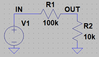
Here is the basic idea, ignoring source and load:
1670776940294.png
Consider the volume control as R1 + R2 with a total resistance of 110 k ohms. In this case, it shows a very low level, with 100k in series and 10k to ground, with IN from the source and OUT going to the power amp. If you decrease the volume, then at the end (lowest volume) R1 = 110k ohms and R2 = 0 ohms, so no signal gets to the output. At that point IN "sees" 110k and the power amp's inputs sees 0 ohms. As you turn up the volume, R1 decrease and R2 increase, so at maximum volume R1 = 0 ohms (IN connects to OUT) and R2 = 110k ohms (just a shunt across the IN and OUT terminals). IN and OUT both see 100k ohms to ground, so the amp sees the input source impedance (usually low) and the source sees the amp's input impedance (usually high) in parallel with (shunted by) 110k ohms. In between the impedances seen by the source and load vary with the position of the control.

The article I mentioned on ASR shows a family of curves as you vary the control.

Active circuits buffer the output (and perhaps the input) so the output impedance is constant (for all practical purposes) and load seen by the control is very high (so does not affect anything).

I do not know what the OP's LDR circuit looks like. Others I have seen replace R1, R2, or both with an LDR and the resistance is controlled by a voltage or current to the light source that changes the resistance.
 

Mike Lavigne

Member Sponsor & WBF Founding Member
Apr 25, 2010
12,601
11,693
4,410
i have no intentions of joining the tech discussions of this thread as it's over my head. but wondered if the analog optical couplers used by darTZeel 18NS Mk2 preamp had any relevance to these LDR's.

Each input on the Dart pre has its own dedicated gain stage, which remains permanently connected and is activated when required, thus avoiding any kind of switching in the signal path. Likewise, there is no potentiometer or resistor network in line with the audio, volume control being by passive attenuation governed by a dedicated processor via analogue optical couplers, offering 192 steps in increments of 0.5dB.

the dart preamp is battery powered.

there is 11db of gain from the dart pre if the source needs it. mostly i listen around the +3db to -20db range with my sources including 4 separate arms and cartridges, 2 internal phono stages, one external phono pre, a dac, and 2 tape decks.
 

DonH50

Member Sponsor & WBF Technical Expert
Jun 22, 2010
3,961
322
1,670
Monument, CO
i have no intentions of joining the tech discussions of this thread as it's over my head. but wondered if the analog optical couplers used by darTZeel 18NS Mk2 preamp had any relevance to these LDR's.

Each input on the Dart pre has its own dedicated gain stage, which remains permanently connected and is activated when required, thus avoiding any kind of switching in the signal path. Likewise, there is no potentiometer or resistor network in line with the audio, volume control being by passive attenuation governed by a dedicated processor via analogue optical couplers, offering 192 steps in increments of 0.5dB.

the dart preamp is battery powered.

there is 11db of gain from the dart pre if the source needs it. mostly i listen around the +3db to -20db range with my sources including 4 separate arms and cartridges, 2 internal phono stages, one external phono pre, a dac, and 2 tape decks.
I have no idea what darTZeel is doing, they are way over my head price-wise! But passive attenuation sounds like a resistor network of some sort.

Optical couplers pass the signal from one side to the other without a physical wire connection. The input signal modulates a light source that is received by the other side, so there is active circuitry at the input and output. But they could be using them to encode an attenuator. That is, as you turn the knob, it modulates the light source (usually an LED), and the receiver decodes that modulation to control an attenuator that adjusts the volume. There has to be something in the signal path to provide attenuation and that is usually a resistor network, but there are a lot of ways to actually do the switching now. Some schemes use transistor switches to select the attenuation instead of mechanical switches, some look something like a "passive" DAC ladder, and some put a transistor in the signal path so the control circuit effectively adjusts the transistor's resistance to set the volume (again, no actual switch in the signal path). Passive attenuation means something must be in the signal path to reduce the amplitude, and whatever that "something" is it will look like a resistor of some sort. Some passive controls use variable transformers instead, which have their own quirks.

There is nothing particularly wrong with resistors in the signal path; all circuits have them, or their equivalent. The common problems associated with potentiometers (a variable resistor) are that the impedance changes with level, solved by buffering (with an active circuit) if need be (it is not usually an issue, purely passive designs exist), and the control surfaces get dirty over time leading to noise and drop-outs as you adjust the volume. Mechanical switches also get dirty and wear out over time, but it is usually a long, long time when used with low-level signals. A lot of modern volume controls use electronic (transistor) switches to avoid the problems of mechanical switches, implemented in a variety of ways.

The LDR is a light-dependent resistor; its resistance changes depending upon how bright the light is that you shine on it. Instead of changing the value of resistance with a physical knob that moves a wiper across a resistor, you change it with light, contactless. That gets rid of the mechanical knob/switch problem. The light source, often a small LED, is encapsulated (enclosed) with the resistor (LDR) in a little package to prevent external light from affecting it. You adjust the light level, and thus the resistor's value, by applying a control voltage (or current) to the pin on the package connected to the light (LED). No mechanical linkage to get noisy or wear out. The signal path can remain completely passive, but you need a power supply for the control circuit that sets the light level. Thus it is a passive preamp (no amp, however) as far as the signal is concerned, but you still have to plug it into the wall (or use a battery) to control the volume (and electronic switches, if used).

HTH - Don
 
  • Like
Reactions: Steve Williams

About us

  • What’s Best Forum is THE forum for high end audio, product reviews, advice and sharing experiences on the best of everything else. This is THE place where audiophiles and audio companies discuss vintage, contemporary and new audio products, music servers, music streamers, computer audio, digital-to-analog converters, turntables, phono stages, cartridges, reel-to-reel tape machines, speakers, headphones and tube and solid-state amplification. Founded in 2010 What’s Best Forum invites intelligent and courteous people of all interests and backgrounds to describe and discuss the best of everything. From beginners to life-long hobbyists to industry professionals, we enjoy learning about new things and meeting new people, and participating in spirited debates.

Quick Navigation

User Menu

Steve Williams
Site Founder | Site Owner | Administrator
Ron Resnick
Site Co-Owner | Administrator
Julian (The Fixer)
Website Build | Marketing Managersing