Hi All,
I am new here. Looking for some help with a amplifier I built from a kit. Resistor R9 is burnt. Thank you, Greg
OK...This is cool. I figured out how to post a photo of my amp right away. I think I built this amp in 1998 from a kit. The board came "stuffed". I think this a term that is used for a board that has the resistors already soldered on. I would like to replace resistors R8 and R9. I think they go to ground. How do I make certain I do not kill myself repairing this? I will post more photos later of my amp.
(...)
Hi All,
I am new here. Looking for some help with a amplifier I built from a kit. Resistor R9 is burnt. Thank you, Greg
OK...This is cool. I figured out how to post a photo of my amp right away. I think I built this amp in 1998 from a kit. The board came "stuffed". I think this a term that is used for a board that has the resistors already soldered on. I would like to replace resistors R8 and R9. I think they go to ground. How do I make certain I do not kill myself repairing this? I will post more photos later of my amp.
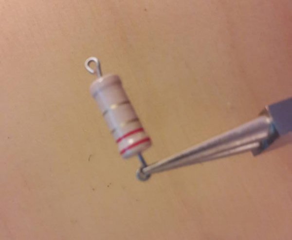
R8 and R9 are the output tube cathode resistors - they can burn in case of a defective tube. If you do not have experience with repairs, do not attempt to remove the resistors - just cut the wires as close to the old resistor body as possible, leaving as much as possible of the wire, and prepare the new resistors as shown. Then solder the resistors, inserting 2 mm of the left wire in the new resistors rings. It does not look nice but it is very often the best way to service old equipment. All IMHO, YMMV.
Equipment should be disconnected from mains when you repair it - and wait a few minutes to let time to the capacitors to discharge before starting the work! Surely the output tubes should be replaced.
Hi Microstrip,
Thank you for your help. I am not the sharpest tack. Could you please tell me what resistor to replace it with? The schematic says 1 watt but the one on the board looks like it says 3 watts
Hi Microstrip,
Thank you for your help. I am not the sharpest tack. Could you please tell me what resistor to replace it with? The schematic says 1 watt but the one on the board looks like it says 3 watts
The resistor will dissipate around 50 mW - a 1 watt one is more than enough. Do not increase it - in case of a problem the resistor works as a fuse. If you increase the power of the resistor you can risk burning the output transformer in case of malfunctioning.
If the amplifier is being used with common current tubes I would change the grid resistors R22, 23, 42 and 43 to 100 kohm or 82kohm. Unfortunately most modern tubes have higher grid leakage current than the NOS types and became unstable with high value grid resistors such as 270kohm.
I had an amplifier sharing a similar circuit with 220 kohm grid resistors, and although it worked fine with NOS selected tubes, it was a nightmare with russian and chinese modern tubes.
The coupling capacitor has a value high enough to support this change.
If the amplifier is being used with common current tubes I would change the grid resistors R24, 25, 44 and 45 to 100 kohm or 82kohm. Unfortunately most modern tubes have higher grid leakage current than the NOS types and became unstable with high value grid resistors such as 270kohm.
Thank you for your help. I cut the resistor out of R9 and I did OK with it. The information on the resistor reads Tepro TS 3W 15.4 1%NI 6550. Could one of you actually Tell me what I should order and where I might get them from? I would like to replace R8, R9, R22, R23, R42 and R43. I think I have some new tubes for another project. I'm uncertain of the brand and uncertain where they are. Can you suggest a tube brand? What is the wattage of Resistor you are suggesting as a 100K ohm? 1 Watt? What should I put in R8 and R9? I understand I should install a 1 watt, but what value should I use? What type of resistor do I order? I just want to get something ordered so I can get it back up and running. Thank you again.
Thank you for your help. I cut the resistor out of R9 and I did OK with it. The information on the resistor reads Tepro TS 3W 15.4 1%NI 6550. Could one of you actually Tell me what I should order and where I might get them from? I would like to replace R8, R9, R22, R23, R42 and R43. I think I have some new tubes for another project. I'm uncertain of the brand and uncertain where they are. Can you suggest a tube brand? What is the wattage of Resistor you are suggesting as a 100K ohm? 1 Watt? What should I put in R8 and R9? I understand I should install a 1 watt, but what value should I use? What type of resistor do I order? I just want to get something ordered so I can get it back up and running. Thank you again.
From where are you getting the resistors? The brand is not critical, although I would select some metal film, between .4 to 1 watt for the grids. If you can not get the 15.6 easily you can associate two resistors to get this value. The output tubes should be close matched, as you can only monitor the sum of the cathode currents.
I shopped Ebay for a quad matched set of Electro Harmonix EL34's. They were $16.00 each. I purchased a matched pair of 6GH8A tubes for $6.00. I purchased 5 each 15 OHM resistors that are 1 watt 5% for R8 and R9. Will these work? I purchased 100K OHM 1 watt resistors for 22, 23, 42, and 43. They were $2.69 for 5 each with free postage. Are Carbon film a bad choice? I do appreciate your help. Once I have the parts in hand the repair should be easy enough. If I can successfully build a Van Alstine Preamp kit, I should be able to do this. I purchased 10 ohm and 5.6 ohm 1watt metal film resistors. How do I best install them? the top one or the bottom one. Thank you
Sorry, I missed your previous post. Happy to know you managed to repair the amplifier. Surely you selected the top (series) association!
Although carbon is considered a noisier resistor some audiophiles prefer them in tube equipment.It is not easy to have a firm answer on this point. The critical point is perhaps the quality of the resistor, not exactly the type.
I asked the question but realized my meter would tell me upon trying the test. I installed a single resistor instead. As above I purchased 100K metal film 1watt resistors for the other four spots. Do you think this will help balance the bias? The adjustable resistor no longer seems to work as intended and the high bias is the only one that will light up. Any suggestions? Thank you for your help.