DSD comparison to PCM.

Based as it is on the TDA1541 architecture, I can't see how anything could be much different. You can quibble about the 7308 versus other tubes, but that's pretty much a subjective decision.

To remember: the TDA chip is still a current output device and needs a fast I/V converter....or a very small resistor if you don't mind all the noise. No tube will come close to the ~1nV/Hz^2 noise of the <100 ohm resistor.

I've had good luck with Pure Music converting 128fs DSD to 24/88.2 PCM ... what I heard sounded like very, very good DSD, despite the fact I what was actually listening to was a pure ladder converter with no noise-shaping at all. If the Zanden accepts an external USB input, or you're OK with S/PDIF -> USB adapters (I've heard the JKenny unit is one of the best, and he's right here on the forum), you can always try software conversion from DSD to high-quality PCM and draw your own conclusions.

In this case, Lynn, the ladder converter is playing noise shaped DSD converted to PCM, so we are still listening to noise shaping even in this scenario; it's really hard to get away from it in the (present) land of digital.

You might be surprised how good it sounds; I now think one of the reasons DSD -> PCM conversion has gotten a bad reputation is that the cheaper delta-sigma converters don't do a very good job of it. Same story for upsampling; high-quality software conversion seems to sound a lot better than old-school hardware-based oversampling, which was a pretty crude process.

I imagine that any converter would do a less than stellar job converting DSD to PCM if it's also trying to do sample rate conversion to 96/24, which is often chosen as a default hi-res format. Even pros record in 96/24 in spite of the fact that virtually all music releases end up as 44.1!
 
To remember: the TDA chip is still a current output device and needs a fast I/V converter....or a very small resistor if you don't mind all the noise. No tube will come close to the ~1nV/Hz^2 noise of the <100 ohm resistor.

how does one check if a piece of equipment has a fast i/v converter or not? what specs/equipment is one looking for in reviews, etc.
 
how does one check if a piece of equipment has a fast i/v converter or not? what specs/equipment is one looking for in reviews, etc.

There are three ways to deal with the fast edges that come out of a current-mode converter:

1) Passive current-to-voltage conversion with a resistor combined with a cap as a lowpass filter with a turnover around 70~100 kHz. Although it's only a 1st-order rolloff, it reduces the magnitude of 1 MHz by 20 dB, and 10 MHz by 40 dB. This is adequate to protect the following gain stage from slewing. It is still good practice to have a 1:2 or 1:3 safety margin between the lowpass filter and the full-power bandwidth of the first active stage. The following stages can implement additional lowpass filtering to prevent ultrasonic images from degrading power-amplifier performance.

Passive conversion is out of favor with most digital designers because the S/N ratio is not as good as active conversion. The app note from the chip vendor usually recommends a pretty slow op-amp performing both active conversion and active lowpass filtering.

2) Active conversion; if this approach is chosen, the slew rate should be 600V/uSec or higher, possibly as high as 2000V/uSec, depending on how much ultrasonic content is present. Conventional feedback topologies are not well suited to operating in the radio-frequency band. Since the active converter has very extended bandwidth, additional filtering in the following stages is mandatory to prevent RFI from entering the following linestage or power amplifier.

3) A very wideband amplifier can be used with the passive-conversion approach for additional HF headroom, and HF rolloff can implemented with a studio-grade transformer between the DAC and the linestage or power amplifier. This rolls off the HF around 50 kHz at a 2nd-order rate, and also breaks the ground connection between the digital and analog devices. Transformer isolation also prevents ground loops between components, giving a very silent and buzz-free background. Rowland Research has successfully combined ultrawideband opamps with transformer coupling for many years now.

The sad thing is many reviewers are uninterested or uninformed about the topology of the analog section ... but you can't blame them when the manufacturer chooses to keep the topology secret. Open up many high-priced DACs, and you see mystery devices with the part number ground off, so it's anyone's guess how it works.
 
1) Passive current-to-voltage conversion with a resistor combined with a cap as a lowpass filter with a turnover around 70~100 kHz. Although it's only a 1st-order rolloff, it reduces the magnitude of 1 MHz by 20 dB, and 10 MHz by 40 dB. This is adequate to protect the following gain stage from slewing.

Since I've not had good results, sound-wise with this approach it follows that there must be some flaw(s) in the analysis. One could be that a capacitor's self resonance is going to be below 30MHz, above this frequency it will no longer attenuate the output from the DAC and current DACs have output above this frequency. Another could be that the non-linearity being excited is not slewing but perhaps RF rectification effects in the LTP as outlined in the paper I shared on another thread recently.
 
There are three ways to deal with the fast edges that come out of a current-mode converter:

1) Passive current-to-voltage conversion with a resistor combined with a cap as a lowpass filter with a turnover around 70~100 kHz. Although it's only a 1st-order rolloff, it reduces the magnitude of 1 MHz by 20 dB, and 10 MHz by 40 dB. This is adequate to protect the following gain stage from slewing. It is still good practice to have a 1:2 or 1:3 safety margin between the lowpass filter and the full-power bandwidth of the first active stage. The following stages can implement additional lowpass filtering to prevent ultrasonic images from degrading power-amplifier performance.

Passive conversion is out of favor with most digital designers because the S/N ratio is not as good as active conversion. The app note from the chip vendor usually recommends a pretty slow op-amp performing both active conversion and active lowpass filtering.

2) Active conversion; if this approach is chosen, the slew rate should be 600V/uSec or higher, possibly as high as 2000V/uSec, depending on how much ultrasonic content is present. Conventional feedback topologies are not well suited to operating in the radio-frequency band. Since the active converter has very extended bandwidth, additional filtering in the following stages is mandatory to prevent RFI from entering the following linestage or power amplifier.

3) A very wideband amplifier can be used with the passive-conversion approach for additional HF headroom, and HF rolloff can implemented with a studio-grade transformer between the DAC and the linestage or power amplifier. This rolls off the HF around 50 kHz at a 2nd-order rate, and also breaks the ground connection between the digital and analog devices. Transformer isolation also prevents ground loops between components, giving a very silent and buzz-free background. Rowland Research has successfully combined ultrawideband opamps with transformer coupling for many years now.

The sad thing is many reviewers are uninterested or uninformed about the topology of the analog section ... but you can't blame them when the manufacturer chooses to keep the topology secret. Open up many high-priced DACs, and you see mystery devices with the part number ground off, so it's anyone's guess how it works.

Thanks! Wish I could figure out what Zanden is using. Just curious to learn more than anything else. I also note that Audio Note made a big deal of putting their M10 preamp into their latest DAC...besides marketing, is this somewhat related to what you are discussing here (ie, their best analog, amplifier section being used inside the DAC?) sorry...total non-techie disclaimer!
 
Since I've not had good results, sound-wise with this approach it follows that there must be some flaw(s) in the analysis. One could be that a capacitor's self resonance is going to be below 30MHz, above this frequency it will no longer attenuate the output from the DAC and current DACs have output above this frequency. Another could be that the non-linearity being excited is not slewing but perhaps RF rectification effects in the LTP as outlined in the paper I shared on another thread recently.

Good question. I have not auditioned a passive I/V driving a transistor long-tailed pair; the only ones I've heard used a RF-type vacuum tube (6DJ8) in a non-feedback circuit, which is linear right through television broadcast frequencies. The care and feeding of transistor circuits in the 1~50 MHz range is well outside my range of expertise; the only circuits I can think of might use FETs in cascode, or some kind of grounded-gate circuit.

Lloydelee21, the requirements for the analog stage are somewhat more severe than a phono preamp. True, noise isn't as much of a consideration, and there's no troublesome RIAA equalization, but dealing with the ultrasonic content is much more difficult. It is true that many phono preamps don't handle mistracking from the MC cartridge all that well (which can clip the preamp), but the continuous onslaught of ultrasonic noise from the converter makes harsher demands on the analog stage.
 
Lloydelee21, the requirements for the analog stage are somewhat more severe than a phono preamp. True, noise isn't as much of a consideration, and there's no troublesome RIAA equalization, but dealing with the ultrasonic content is much more difficult. It is true that many phono preamps don't handle mistracking from the MC cartridge all that well (which can clip the preamp), but the continuous onslaught of ultrasonic noise from the converter makes harsher demands on the analog stage.

Thanks, Lynn...i thought i read that the M10 (maybe its the M9) that Audio Note use in their DAC is actually their reference level preamp...in other words they put the entire preamp into the DAC other than volume control. Is this any better?
 
;)
Well, it's the yardstick that matters, doesn't it? If the criterion is movie soundtracks, that's a completely different thing. Since soundtracks are completely artificial confections, there's really no reference at all, unless you work at Skywalker Ranch in California, and have ready access to their theater.

I live 4 miles from Skywalker Ranch, but cannot get into his theater.;)
 
Last edited:
Thanks, Lynn...i thought i read that the M10 (maybe its the M9) that Audio Note use in their DAC is actually their reference level preamp...in other words they put the entire preamp into the DAC other than volume control. Is this any better?

IMHO, no. Keep them seperate due to, as Lynn pointed out, harshness from subsonic noise.
 
how does one check if a piece of equipment has a fast i/v converter or not? what specs/equipment is one looking for in reviews, etc.

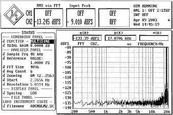
As Lynn says, the opamps often have their markings rubbed off, so all bets are off as to what part has been used. But looking at the two-tone response, 19KHz + 20KHz at -6dB FS can reveal a lot about the I/V performance. A dac with an adequate I/V will show sum and difference harmonics in the -110 to -120dB range.

While this is strenuous test for the entire output chain, Kieth Johnson (Mr. HDCD) used a multi-tone cluster at the top of the audio band and tuned for -120dB FS for all harmonics in the Models 1 and 2, both adc and dac. To see the dac distortion required using an LC band-reject filter ahead of the analyzer to avoid its generating additional artifacts.
 
There are three ways to deal with the fast edges that come out of a current-mode converter:

2) Active conversion; if this approach is chosen, the slew rate should be 600V/uSec or higher, possibly as high as 2000V/uSec, depending on how much ultrasonic content is present. Conventional feedback topologies are not well suited to operating in the radio-frequency band. Since the active converter has very extended bandwidth, additional filtering in the following stages is mandatory to prevent RFI from entering the following linestage or power amplifier.

The use of a FET input opamp somewhat mitigates the need for extreme slew capability at the expense of some noise penalty over a good bipolar design. Choose one that has good settling time behavior as well. Follow that with some passive low-pass filtering.
 
While this is strenuous test for the entire output chain, Kieth Johnson (Mr. HDCD) used a multi-tone cluster at the top of the audio band and tuned for -120dB FS for all harmonics in the Models 1 and 2, both adc and dac. To see the dac distortion required using an LC band-reject filter ahead of the analyzer to avoid its generating additional artifacts.

Here's the result for my particular Model Two (courtesy of Dave Peck):

ADC Multisine Test low-res.jpg

Mani.
 
how does one check if a piece of equipment has a fast i/v converter or not? what specs/equipment is one looking for in reviews, etc.

As Lynn says, the opamps often have their markings rubbed off, so all bets are off as to what part has been used. But looking at the two-tone response, 19KHz + 20KHz at -6dB FS can reveal a lot about the I/V performance. A dac with an adequate I/V will show sum and difference harmonics in the -110 to -120dB range.

While this is strenuous test for the entire output chain, Kieth Johnson (Mr. HDCD) used a multi-tone cluster at the top of the audio band and tuned for -120dB FS for all harmonics in the Models 1 and 2, both adc and dac. To see the dac distortion required using an LC band-reject filter ahead of the analyzer to avoid its generating additional artifacts.

Thanks for that...i will try to re-read and understand a bit more though Opus might need to translate into something super dumbed down for non-techies like me.
 
Keith used the Rohde & Schwarz but preceeded it with a passive LC notch filter; as I remember, the front end was only good to about -110dB.

The FFT processing gain here I reckon is 33dB and the 'floor' looks to be -135dB, there's 6 averages which will lower that another 6dB or so. So yeah I reckon that there's slight modulation of the analyser floor as the noise looks to be around the 17bit level at the low end, worse at higher freqs.
 
New article out at Positive Feedback:
http://www.positive-feedback.com/Issue66/pcm_dsd.htm

I'm pretty sure that the proposed dither-noise spectra would change the sound of mid-to-upper-mid delta-sigma DACs in some kind of way (maybe worse, maybe better). Class D amplifiers improved quite a bit when spread-spectra modulation (octave-wide ultrasonic noise) replaced a single ultrasonic tone; I'm guessing that opamps would also respond to the same approach. If you gotta have slewing, better to spread it around evenly.

Of course, it's better not to have slewing, but that costs more.

P.S. The title is partly tongue-in-cheek. I don't think this technique is going to make a generic audiophile DAC sound like a Playback Designs with 128fs DSD source. No. But I do think it'll make PCM on a mid-grade DAC sound better ... well, more "analog-like", which can be taken several different ways.

I suspect mid-grade DSD DACs mimic the modulation noise of 2-track 15ips analog tape, thanks to all that randomized distortion. Magazine reviewers trip off on that sound, and associate it with "analog".
 
Last edited:
Yeah its a funky idea but I'll not be trying it any time soon in my DAC designs. Firstly because mine are NOS, there's no available space in the spectrum to insert the high level dither. And secondly because you omitted to mention that having all that HF means the multibit DAC is now much more sensitive to jitter. Jitter causes the HF noise to fold down into the audio band once again, giving rise to noise modulation. So yes it will help multibit DACs to sound more like S-D ones, in that now there's much more noise modulation and not only from the jitter. Effectively, adding HF noise means the average inter-sample step sizes from the DAC grow enormously - bigger steps mean bigger dynamic errors and this translates to poorer SNR. But perhaps there is an upside - the noise, though higher won't be modulated by the signal content so much, the HF noise will tend to decorrelate it.
 
Well, it really does combine some of the worst features of PCM and DSD. All the noise of DSD, and the transient response of PCM. Probably very similar to what you get when studio-origination PCM is "upsampled" to SACD or DSD; all of the time-domain problems from the original PCM encoding remain, and a lot of ultrasonic noise is added.

High-quality multibit converters would probably be degraded, but mid-quality delta-sigma converters might sound better. The steady noise level would prevent low-level instabilities in the noise-shapers, and delta-sigma converters are designed to operate at high ratios of oversampling, which facilitates a high dither frequency. In a sense, the much higher level of dither forces the delta-sigma converter closer to a DSD mode of operation, while avoiding the stability problems of a physical one-bit converter.
 

About us

  • What’s Best Forum is THE forum for high end audio, product reviews, advice and sharing experiences on the best of everything else. This is THE place where audiophiles and audio companies discuss vintage, contemporary and new audio products, music servers, music streamers, computer audio, digital-to-analog converters, turntables, phono stages, cartridges, reel-to-reel tape machines, speakers, headphones and tube and solid-state amplification. Founded in 2010 What’s Best Forum invites intelligent and courteous people of all interests and backgrounds to describe and discuss the best of everything. From beginners to life-long hobbyists to industry professionals, we enjoy learning about new things and meeting new people, and participating in spirited debates.

Quick Navigation

User Menu

Steve Williams
Site Founder | Site Owner | Administrator
Ron Resnick
Site Co-Owner | Administrator
Julian (The Fixer)
Website Build | Marketing Managersing