64 Cell (8x8) PRD (Skyline Diffuser) question

kareface

New Member
Jul 30, 2010
91
0
0
Seattle, Wa
RPG owns PRDs. The foam skyline they produce is a prime 157 13x12 PRD with the 13 length coloumns being 12/13 times the width of the 12 length rows, thereby making it square. The HF cutoff is different depending on direction.
I think we are talking about different products. If my memory serves me it was a rigid plastic, not a foam.

"This is illustrated in figure 9.4 where the scattering from diffusers of different period widths is shown. These are both n=7 QRD's with a design frequency of 500 Hz. The well widths are 3 and 9 cm, which means that the period widths are 21 and 70cm respectively. The number of periods for each diffuser is set so that the overall widths of the devices are the same for a fair comparison. For the narrow wells and period width, shown right, the low frequency limit of diffusion is determined by the period width and not by the maximum depth."
You keep posting quotes that don't have any bearing on your argument. This once again does not prove your point. I've agreed many times over that cell depth and period width are correlated. However, this doesn't prevent the width of the device from being extended by another diffuser. The reason the diffuser is ineffective at that frequency is sound waves that low CAN'T reflect off the surface, so it's only natural that the cutoff will occur. The same is true of any diffuser. Geometric diffusers have to have a surface area relative to the length of the target low as well. You can also extend their lows by using them in conjunction with each other, and they actually scatter more effectively when you use several smaller alternating shapes. All you're proving is that an individual diffuser has to be long enough to handle the low. If you use more than 1 diffuser the target low can be extended.

Let me guess: the diffusers where suspended lower than the rest of the ceiling, not flush mounted? (or ditto scenario on a wall) The sides of the diffusers are pretty much flat reflecting panels. I have also seen the detrimental results of the flat sides when measuring the performance of those devices in real rooms. At one stage, I ended up treating the offending specular refleciton with two pieces of 4" foam on the sides of the two diffusers that where problematic in that setup.
In the case I referred to they were 3 large diffusers on casters at the rear of the room. How we ended up correcting for them was spacing them out, filling the gaps with some bass traps designed for corner use and placed an MPD suspended from celinging slightly above the center diffuser angled at the primary listening position. For some reason neither the spacing nor the added diffuser alone was enough. If you have any thoughts as to why I'd love to hear. I haven't managed to put this one together myself.

This doesn't mean the math is useless for a single device.
Don't get me wrong, I don't think the equation is pointless. I'm just comparing the objective of the math and the potential outcomes.

I think of it like this: perfect math gives real world results approaching perfect at best. Bad math will by definition be worse off to start with.
Yes, if we were talking about QED I would completely agree. The mathematics in that case would directly correlate to the output. However, people get caught up in numbers that don't necessarily represent a direct manifestation of the results. This is at best indirect, because the math represents a random pattern that increases the probability of scattering. I agree that truncating it will not produce the same results, I'm just questioning the impact.

The degree of randomness is quantifiable through the math!
Yes, I completely agree with this. Just simply being random doesn't necessitate results. It does improve the chances, but there isn't a direct causal relation. It's possible (even likely) for 2 permutations to be more or less effective.

I've read the patent and didn't read that into it. Can you point to the specific trial and error you think about?
I reread the line and now that I consider it I think when he mentioned "yield these results" he's referring to that permutation as opposed to the intended results. It's rather vague as to the meaning, but I believe I was mistaken.
 

Nordenstam

New Member
Aug 18, 2010
37
0
0
Norway
nordenmaster.no
I think we are talking about different products. If my memory serves me it was a rigid plastic, not a foam.

It's rigid plastic; styrofoam. With a density of 32 kg/M^3 if I recall correctly. It's pretty hard to compress by hand. RPG owns the patent on PRD's and is the sole producer of these products. http://www.rpginc.com/products/skyline/index.htm - notice the 13x12 pattern is a square.

You keep posting quotes that don't have any bearing on your argument. This once again does not prove your point. I've agreed many times over that cell depth and period width are correlated. However, this doesn't prevent the width of the device from being extended by another diffuser.

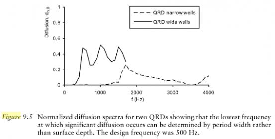
We've reached a standstill. The measurement Cox and D'Antonio provides shows a diffuser that is deep enough to work at 500Hz, but not wide enough to do so(21 cm). Adding more diffusers to extend the overall width doesn't help the situation at all, as seen in the measurement results. If you don't want to aknowledge that, there's nothing I can do about it!

Measurement stolen from Cox and D'Antonios book through Google Books:

thebook..jpg

This is NOT the response from a single diffuser, it's the response from a repeating array of many diffusers. (in this case, 10, 20 or more)


In the case I referred to they were 3 large diffusers on casters at the rear of the room. How we ended up correcting for them was spacing them out, filling the gaps with some bass traps designed for corner use and placed an MPD suspended from celinging slightly above the center diffuser angled at the primary listening position. For some reason neither the spacing nor the added diffuser alone was enough. If you have any thoughts as to why I'd love to hear. I haven't managed to put this one together myself.

It may be that you've seen the effect of periodicity? Several of the same shapes next to each other will produce energy that is lumped into certain lobes. The way to avoid it is to use modulation with something like the inverse of one of the diffusers. A typical modulation scheme is the barker code: http://en.wikipedia.org/wiki/Barker_code - for a repeat of 3 it's + + -.

But I don't know.. Strange result you got, indeed!


Andreas
 

kareface

New Member
Jul 30, 2010
91
0
0
Seattle, Wa
This is NOT the response from a single diffuser, it's the response from a repeating array of many diffusers. (in this case, 10, 20 or more)
Where did you read that it was from an array of 20 or more? I might of missed something, but everything I read suggests that he's only using 2 diffusers in the test. Now that I think about it, the diffusion coefficient values in the graph you posted for a QRD of that width are what you would expect, maybe even a bit low.
 
Last edited:

Mike Lavigne

Member Sponsor & WBF Founding Member
Apr 25, 2010
12,601
11,693
4,410
ok; since i use both RPG Skyline diffusors and Auralex T-Fusor diffusors in my room i figured this thread might offer some helpful details about diffusors....so i innocently took a peek.

holy crap!!!

i would appreciate it if one of you 'smart guys' could interpret the conclusions of your 'exchange' for us with wording we are likely to understand.

btw; i would love to invite you guys from Seattle to come and visit me in North Bend and see if you have any advice for my room. we can even actually listen to music if you like.:D
 

kareface

New Member
Jul 30, 2010
91
0
0
Seattle, Wa
At this point in the thread we're just debating the hypothsis of using mutiple diffusers which are desgined to be effective to a target frequency, but are limited based on their surface area, if they will still scatter when used in conjunction.

btw; i would love to invite you guys from Seattle to come and visit me in North Bend and see if you have any advice for my room. we can even actually listen to music if you like.:D
Sure, I can bring some calibration hardware with me and do a simple overview of the room. North bend is a ways out there tho.
 

Mike Lavigne

Member Sponsor & WBF Founding Member
Apr 25, 2010
12,601
11,693
4,410
At this point in the thread we're just debating the hypothsis of using mutiple diffusers which are desgined to be effective to a target frequency, but are limited based on their surface area, if they will still scatter when used in conjunction.

Sure, I can bring some calibration hardware with me and do a simple overview of the room. North bend is a ways out there tho.

i have some nice Scotch, a few nice tt's, and tape decks with some dubs of master tapes which hopefully might tempt you. and i'm just off exit 31 in North Bend.....30 minutes from downtown with light traffic. it's actually faster than getting to Redmond from in Seattle because I-90 is so direct and i'm only 5 minutes off the freeway.

oh, and thanks for the translation. i hope i get the chance to discuss the performance of the diffusers i have in my room with you.
 

Nordenstam

New Member
Aug 18, 2010
37
0
0
Norway
nordenmaster.no
i would appreciate it if one of you 'smart guys' could interpret the conclusions of your 'exchange' for us with wording we are likely to understand.

Just trying to point out that sticking to established design guidelines may be a good idea. :)


kareface said:
Where did you read that it was from an array of 20 or more? I might of missed something, but everything I read suggests that he's only using 2 diffusers in the test. Now that I think about it, the diffusion coefficient values in the graph you posted for a QRD of that width are what you would expect, maybe even a bit low.

I'm well aware that one reads what one wants to read. It is however too explisit for me to doubt in this case. Have read The Book over and over, across many years. It'll always be extremely handy to have around as it's the most comprehensive source of information on absorption and diffusion in my library. Well worth the price! The diffuser theories generally deals with periodic repetetions of diffusers, not the response from a single diffuser. When Cox and D'Antonio writes "a diffuser", they mean a periodic array of a diffuser. Periodicity is a requisite for the expected results to appear. Figure 9.6 is the exception as this illustrates a single period vs periodic devices. This is the paragraph after the one on repeat width. If google books works for you it's here to read: http://books.google.no/books?id=f19...f the period width (Nw) is too narrow&f=false


The periodicity and the reason I assume 2.1 meter width or multiplies thereof is mentioned here:

"This is illustrated in figure 9.4 where the scattering from diffusers of different period widths is shown. These are both n=7 QRD's with a design frequency of 500 Hz. The well widths are 3 and 9 cm, which means that the period widths are 21 and 70cm respectively. The number of periods for each diffuser is set so that the overall widths of the devices are the same for a fair comparison. For the narrow wells and period width, shown right, the low frequency limit of diffusion is determined by the period width and not by the maximum depth."

The subtitle to figure 9.4: "Overall width kept the same by changing number of periods".

If the overall width of the two different diffuser arrays are the same, the arrays are ten 21cm panels and three 70cm panels, or twenty 21cm's and six 70cm's, etc.


The Trevor Cox text also deals with repetitions:
"If the aim of a diffuser is to generate reflected energy at oblique angles, it is necessary for the diffuser to have a period width (or repeat distance) larger than the wavelength of the lowest frequency where scattering is required. For a periodic device, having the width equal to the wavelength means that three reflection lobes are generated in the directions - 90º, 0º and 90º (relative to the surface normal). Some socalled diffusers, produce no significant scattering over the bandwidth expected, because the bandwidth has been assumed to be defined by the diffuser depth, and no account of the period width has been taken." http://www.rpginc.com/news/library/tyndall_paper.pdf
 

kareface

New Member
Jul 30, 2010
91
0
0
Seattle, Wa
Let me start by mentioning I own a hard copy of that book, that wasn't what I was referring to when I was asking where you got that idea from.

Something's odd about what you posted, the period widths don't match the cell widths. A QRD that's N=7 with a target low of 500hz and has a well width of 3cm would be 21cm. However the larger well width of 9cm would have a period width of 63cm, not 70. Second, even if the sequence wasn't ideal there should be a diffusion coefficient above 0 for the narrow cell diffuser. Any complex geometric shape wide enough to produce reflections at the target wavelength will produce some measurable results in the far free-field polar response. There's just no way that on that surface a waves that low would radiate in phase above the length limitation. Before derivative based optimization existed diffusers still produced measurable output, if the exact criteria isn't met the device doesn't just stop working. The only time you see results like that graph cited is when the sum of the diffusers is too narrow. Either some of the context of the test is being left out or there's some other influence like quarter wavelength resonance. It's 6am here and I gotta leave, but I'll pick this back up when I get a break.
 

Nordenstam

New Member
Aug 18, 2010
37
0
0
Norway
nordenmaster.no
Something's odd about what you posted, the period widths don't match the cell widths. A QRD that's N=7 with a target low of 500hz and has a well width of 3cm would be 21cm. However the larger well width of 9cm would have a period width of 63cm, not 70.

Heh. So much for trying to be a math geek..

While 6*21=126cm adds up with 2*63cm, it's more likely that they used 10cm wide wells and a 210cm array width. The size cutoff for 500 Hz is 343/500=~69cm. If the repeat width is to be larger than this, wells have to be 10cm's. 9 cm wide wells adds up to a size cutoff of 343/0.63=544Hz, above the design frequency.

(not taking into account the size of the well dividers).

Second, even if the sequence wasn't ideal there should be a diffusion coefficient above 0 for the narrow cell diffuser.

That one is easier to explain. The flat surface response is substracted from the diffusion coefficient values seen in the graph. This is why the level is overall pretty low and why there's nothing happening before ~1600Hz (and ~500Hz). Below that, there's no difference between the diffusers and flat surfaces.
 

kareface

New Member
Jul 30, 2010
91
0
0
Seattle, Wa
Heh. So much for trying to be a math geek..

While 6*21=126cm adds up with 2*63cm, it's more likely that they used 10cm wide wells and a 210cm array width. The size cutoff for 500 Hz is 343/500=~69cm. If the repeat width is to be larger than this, wells have to be 10cm's. 9 cm wide wells adds up to a size cutoff of 343/0.63=544Hz, above the design frequency.

(not taking into account the size of the well dividers).
That came out rather obnoxious of you. First, you are making the assumption that somehow after working out the values for the diffuser width I wouldn't have the low cutoff. Second, it doesn't change the fact the values in the citation are wrong, which was exactly what I was pointing out. I could point out that well dividers can't be used because it would extend the total width of the device in both instances unless he only used them on one of the 2 device, but that would be pointing out something that's obvious and a math geek would never overlook that. It's just not reassuring to have typos in cited examples.

That one is easier to explain. The flat surface response is substracted from the diffusion coefficient values seen in the graph. This is why the level is overall pretty low and why there's nothing happening before ~1600Hz (and ~500Hz). Below that, there's no difference between the diffusers and flat surfaces.
You reiterated the fact there's no difference, which does nothing to address the point. This is exactly why AC is better used for coefficient testing than PR, the methodology is best suited for gauging spatial scattering which QRD's aren't known for. It's physically impossible for a complex geometric structure with a depth deep enough & length long enough to radiate in phase at every frequency in a 1000hz range. It's much more likely that the coefficient values are that low because the repetition effect is more prominent at lower frequencies with greater numbers of diffusers. There isn't a good Barker sequence for 10 QRD diffusers (or 20 for that matter), and ideally above 5 you want to stick with odd numbers of diffusers for ideal output. The cell resonance increase when you narrow the width with out adjusting the depth value to match. He doesn't include the number of period repetitions, the modulated sequences or potential permutations, the results are unrealistically low values, the testing methodology is something he himself has explained was not as effective as AC especially for temporal scattering and we have to make some assumptions about the starting values due to typos (albeit minor ones). You can measure a peak in free-field polar from a bookshelf, there's no way a diffuser that length would produce no measurable scattering. You wouldn't even need a free field to test this, just run a noise generator in a room with an object that was near the size of the wave length with some degree of complex geometry. Even with out using PR or SC there will be a measurable difference in response given enough surface area. I'm not saying the results are wrong, I'm saying something is being left out.
 

terryj

New Member
Jul 4, 2010
512
0
0
bathurst NSW
That came out rather obnoxious of you.

you seem quick to take offense. dunno why, I have experienced it as well in this thread. I mean it doesn't bother me too much, but it does seem to be counter productive. Not that I know andreas personally ( but netically haha, I just made up a new word) but to my mind he is one of the true helpful gentlemen, very much a fire puterouter (another new word) than a fire starter.

I have no doubt it was a self deprecating remark.
 

kareface

New Member
Jul 30, 2010
91
0
0
Seattle, Wa
I have no doubt it was a self deprecating remark.
I don't see a context where that would make sense. Unlike your posts where there was some ambiguity about the tone, I didn't see that here. I assumed that's what he meant at first, but I was unable to see a way the context represented it.

Something dawned on me. You know why the values don't add up, it's because it isn't a 2D diffuser. It explains why there isn't any information on the modulated sequence, why you wouldn't need to eliminate cell resonance and why the efficacy difference is so dramatic. If that's the case I actually wouldn't disagree with what he has to say.
 

Nordenstam

New Member
Aug 18, 2010
37
0
0
Norway
nordenmaster.no
It was written with self irony. Actually had one of the rare occasions where I did the literal laugh out loud. I'm the one pretending to be math geeky in this thread, so it's not that bright to have a 7 times 9 situation and let the 70 result slip by, eh? :)

Something is odd in the description, indeed. For all I know, the results presented may be generated through boundary element modelling where divider width can be zero. One of the parameters is still wrong in the text, I know, but I don't find that to be much of a trouble as it still describes the general idea.

There are plenty of similar graphs in The Book with nothing happening before it reach some threshold. Check chapter four on the subject. The same lack of low end effect can also be seen in the geometrical scattering chapter, where too short repeat distance will dominate the low end behaviour.

Put it this way: what sort of scattering do you expect from a surface with too short repeat distance? Never mind the shape of the scattering elements(pyramids, 1D QRD's, 2D PRD's etc), just look big at it..
 

kareface

New Member
Jul 30, 2010
91
0
0
Seattle, Wa
Sorry if I misinterprated your comment, it's just hard to imagine that in a positive context. I'll take a look at the design when I get a chance, I really wish the images of it were a little larger, lol.
 

kareface

New Member
Jul 30, 2010
91
0
0
Seattle, Wa
It's obviously a series of smaller QRD's rotated then placed at different heights. The structure is arranged in an 8x8 pattern of QRDs, and it's clear that low cutoff isn't dependent on any individual QRD's cell depth or period width. I can't think off hand of any combination of QRD patterns that would come out to 8x8 with out truncation, there doesn't seem to be enough diversity in height to be using a PRD pattern unless they are really small cell quantities. I'll have to think over the pattern a little, I don't know how they decided to arrange the QRD heights.
 

kareface

New Member
Jul 30, 2010
91
0
0
Seattle, Wa
In case anyone was curious, the panels are finished. Still working on the bass trap and haven't started the resonators.


kareface

New Member
Jul 30, 2010
91
0
0
Seattle, Wa
That's false, QRD's do not need to be symmetrical.


2D panels modulated - nine asymmetrical N5 2D QRD panels with three rotated. You can shift the position of the pattern, test it out with any 2D QRD generator.
 

About us

  • What’s Best Forum is THE forum for high end audio, product reviews, advice and sharing experiences on the best of everything else. This is THE place where audiophiles and audio companies discuss vintage, contemporary and new audio products, music servers, music streamers, computer audio, digital-to-analog converters, turntables, phono stages, cartridges, reel-to-reel tape machines, speakers, headphones and tube and solid-state amplification. Founded in 2010 What’s Best Forum invites intelligent and courteous people of all interests and backgrounds to describe and discuss the best of everything. From beginners to life-long hobbyists to industry professionals, we enjoy learning about new things and meeting new people, and participating in spirited debates.

Quick Navigation

User Menu

Steve Williams
Site Founder | Site Owner | Administrator
Ron Resnick
Site Co-Owner | Administrator
Julian (The Fixer)
Website Build | Marketing Managersing