Request Help Identify Parts Of Lynx AES16

canoosa

VIP/Donor
Jun 4, 2011
10
0
0
Greetings All,

In an effort to eliminate/control emi/rfi emissions within the server (in order to improve the quality of playback), locating sources of strong emissions is important.

Does anyone know and can identify the following parts on a Lynx AES16 sound card, using the included picture as a reference?

1) the VRM 2) the DAC 3) switching regulator(s) 4) a clock, if any such discrete unit is used on this card

I did contact Lynx asking for this info but they simply refused to provide it, and I have no idea why; am guessing these details are deemed "trade secrets" or "classified".........???

Anyway, any and all help would be much appreciated.
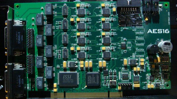
Lynxcard 007.JPG
 

dallasjustice

Member Sponsor
Apr 12, 2011
2,067
8
0
Dallas, Texas
It doesn't have a DAC. :confused:


Greetings All,

In an effort to eliminate/control emi/rfi emissions within the server (in order to improve the quality of playback), locating sources of strong emissions is important.

Does anyone know and can identify the following parts on a Lynx AES16 sound card, using the included picture as a reference?

1) the VRM 2) the DAC 3) switching regulator(s) 4) a clock, if any such discrete unit is used on this card

I did contact Lynx asking for this info but they simply refused to provide it, and I have no idea why; am guessing these details are deemed "trade secrets" or "classified".........???

Anyway, any and all help would be much appreciated.

View attachment 20953
 

dallasjustice

Member Sponsor
Apr 12, 2011
2,067
8
0
Dallas, Texas
Note the FPGA at the bottom of the board.

Uhm, there's still no DAC chip on that board. It's not a DAC! It's a digital interface. An FPGA is not a DAC chip. The FPGA is there for routing channels. There's a mixer interface. This is designed for pro audio.

Also, I've owned a lot of Lynx gear. It's very unlikely the OP will be able to modify this board to get any type of benefit. Lynx makes very high quality and well designed gear. That's why they didn't respond to the question the OP posed to Lynx.
 

canoosa

VIP/Donor
Jun 4, 2011
10
0
0
mep - I'm assuming that the Xilinx Spartan functions in somewhat the same capacity as a DAC? Iot, the Spartan is a source of strong radiation........
 

canoosa

VIP/Donor
Jun 4, 2011
10
0
0
dallasjustice - I had made it clear to Lynx that I was not casting aspersions or in any manner impugning lack of quality; on the contrary, I specifically indicated that I think they make very good stuff.
However, adherence to high standards does not necessarily equate to lack of radiation, which is the basis of my wanting the information requested, nor does it imply making modifications per se.
 

dallasjustice

Member Sponsor
Apr 12, 2011
2,067
8
0
Dallas, Texas
If you don't know the basics about what the AES16 is, how is that you know that you can improve the design?

dallasjustice - I had made it clear to Lynx that I was not casting aspersions or in any manner impugning lack of quality; on the contrary, I specifically indicated that I think they make very good stuff.
However, adherence to high standards does not necessarily equate to lack of radiation, which is the basis of my wanting the information requested, nor does it imply making modifications per se.
 

dallasjustice

Member Sponsor
Apr 12, 2011
2,067
8
0
Dallas, Texas
mep - I'm assuming that the Xilinx Spartan functions in somewhat the same capacity as a DAC? Iot, the Spartan is a source of strong radiation........

I understand why you and Mark are confused. I'm sure you've seen DAC boards with an FPGA on the board. However, the FPGA CANNOT function as a DAC. It's just a computer. It's no different than saying that an Intel chip is DAC. It's just a digital processor.
 

amirm

Banned
Apr 2, 2010
15,813
38
0
Seattle, WA
Greetings. That card is an AES/EBU digital I/O interface. It has no onboard DACs. The DAC would be external.

I am happy to document what is there though if you like me to do that.

And FPGA is digital interface logic (programmable). It does not perform any DAC functionality.
 

FrantzM

Member Sponsor & WBF Founding Member
Apr 20, 2010
6,455
29
405

canoosa

VIP/Donor
Jun 4, 2011
10
0
0
Greetings Amir,

I would love to know what/where the specific parts are!

Again, please let me reiterate what I'd started with, that the question(s) here is set within a context of eliminating/controlling emi-rfi radiation. I have NO desire to make any changes to the excellent unit's design. My sole concern is radiation and its deleterious effects on playback quality, regardless of the source within the server, whether from a processor (e.g. Intel cpu), a DAC, or whatever. Think of Ack's excellent postings re his system on WBF pertaining to electronic noise (and the initial impetus for my current pursuit); the only difference here is that my system is entirely digital.
 

amirm

Banned
Apr 2, 2010
15,813
38
0
Seattle, WA
Here is a mark-up of the parts. The rest are pretty hard to read in those images.


Basic flow is at the bottom PCI interface. Data from the computer comes up through there, it goes through the heart of the board which is the FPGA. It handles the PCI protocol and separates the traffic for each of the 16 digital AES/EBU channels. The AES/EBU is implemented using the AKM4116 digital I/O transceivers. Their output goes into DS26LV31 line drivers (think of them as little amplifiers). The in turn go into the transformers on the left.

Since PCI bus and AES/EBU channels run at different speed, there is a 2 mbit SRAM that is at the bottom to the left of the FGPA. That and FPGA are the highest speed components on the board.

As for clock source, it is either derived from PCI or locally generated. I can't read the part numbers for the smaller parts so can't tell for sure but the little square cans may be the ones.

Again, this is a digital interface board. It is used to drive DACs that accept balanced digital inputs. As noted, there is little you can do to modify it. I suppose you could put shielding around the whole thing but a) you have to be careful to not short out anything else and b) you have no idea if that noise is bleeding out that way. And the whole project would require fair bit of expertise.
 

amirm

Banned
Apr 2, 2010
15,813
38
0
Seattle, WA
Greetings Amir,

I would love to know what/where the specific parts are!

Again, please let me reiterate what I'd started with, that the question(s) here is set within a context of eliminating/controlling emi-rfi radiation. I have NO desire to make any changes to the excellent unit's design. My sole concern is radiation and its deleterious effects on playback quality, regardless of the source within the server, whether from a processor (e.g. Intel cpu), a DAC, or whatever. Think of Ack's excellent postings re his system on WBF pertaining to electronic noise (and the initial impetus for my current pursuit); the only difference here is that my system is entirely digital.
I realize this is what you want to do but RF signals are invisible (well, duh! :D). They bleed physically and through the air. Even expert designers cannot look at a design and determine where such leakage exists. They use a spectrum analyzer with a probe (antenna really) and use it to analyze where the strongest signals are, and what frequency.

How were you going to quiet a naked board like this anyway? Best bet is to put the whole thing in a nice, sealed PC case, preferably one that you commercial bought, not built.
 

dallasjustice

Member Sponsor
Apr 12, 2011
2,067
8
0
Dallas, Texas
If the goal is to reduce the supossed negative effects of RFI/EMI, you could place the PCI card in a magma case made for this purpose. It has its own power. I doubt there will be any improvement in sound quality.
http://magma.com

Btw, PCI is a pretty outdated interface, so you would have been able to find more expansion boxes for PCIE. Lynx makes the aes16e which would be a little easier for what you want to do.

Of course, you haven't mentioned what kind of DAC you are using. Most quality DACs made in the last 3-4 years will use a far superior digital interface than AES/EBU. The difference can actually be measured with jitter tests.
 

canoosa

VIP/Donor
Jun 4, 2011
10
0
0
Thank you so much, Amir, for that helpful delineation and outline!

One option is to seal it within a cage of emi absorbers (e.g. 3M AB7050 or Ab5100S, although they are only available by special order, these days), but that precludes using Anti-Vibration Magic paint, another "essential" for reducing the effects of so-called super-micro vibration initiated by giga/mega hertz freqs.
HOWEVER, in view of what has been defined as a non-DAC function for the Spartan FPGA, perhaps I'll take a chance and coat the specific areas of the board prior to creating the cage, with more specific, tiny layers of absorber on the "clocks" and/or Spartan.
EVERYTHING in the server will be treated, one way or the other (i.e. absorbing or shielding, or both) from the case through mobo (both sides) through psu, etc, including sata cable. Some of the material we have on hand is mu-metal, copper mesh, lots of high quality absorber sheets, Kapton tape, ni/cu/co tape and cloth, and more. As for the expertise.........well, there's lots of experience with a very large variety of tools in a large variety of fields, but for this application there is very little - apart from a complete lack of fear and a great deal of prior homework/study, and basic logic. We work according to two mottos: Do it right the first time & Use the right tool for the job.
The server that we have on hand is a fine example for what NOT to do, and by the time we're done (my wife and I do EVERYTHING together), we'll be running a server based on Intel's Xeon E3-1231v3 with WS2012 R2 Standard as the OS. I'd had everything more or less ordered and figured except for info on the AES16, which is in our current server and and the only component to be transferred.

I DO thank you for helping, Amir, I've always greatly appreciated your input here, and have been a quiet bystander for some while. In fact, there are a large number of people to thank for all the things I've learned here, what I consider the most reliable source.

I've got some ranch chores to do, back in a couple of hrs.
 

canoosa

VIP/Donor
Jun 4, 2011
10
0
0
Amir - It would appear that the clock is the next largest rectangle to the bottom right of the Xilinx Spartan, which rectangle has R4 on its bottom left and U2 on its top right; even though illegible, the characters are upside down as viewed in the picture.
I had to pull the card in order to read the imprint, and only then with a magnifying glass, followed by an eye loop to confirm the characters.
What is imprinted is the following, with the proviso that you must mentally move the dots in the top, first line to the middle of the writing, rather than what my keyboard reproduces, which is a dot at the bottom of the line (writing):

M.10.000
J1016L
X3HAH

Any chance you can confirm that? I'm also curious on what freq it operates ( I googled the characters - nada!)
 

amirm

Banned
Apr 2, 2010
15,813
38
0
Seattle, WA
First thanks for the kind words :). It is a pleasure to hear such feedback.

Is that the U13 part? If so, yes, it does seem like on oscillator as it has the "M" designation which is for Megahertz. It is saying that it is a 10 Mhz clock. I suspect it goes into the FPGA, and becomes the clock source for the AKM 4114 AES/EBU drivers.
 

canoosa

VIP/Donor
Jun 4, 2011
10
0
0
Super, and knowing the freq helps even more!

Well, that's it then, methinks. My thanks to all the different contributors, too.

And sometime during the interval, just had to have a look at what the "Two White Guys Asking For Money" was all about.......excellent timing on my part, don't you think?

Best Regards, One and All!
 

Tam Lin

Well-Known Member
Mar 20, 2011
97
38
923
79
North Texas
I suspect it goes into the FPGA, and becomes the clock source for the AKM 4114 AES/EBU drivers.

Huh? The clock source for the AKM drivers are the two oscillators on the right hand side of the board, 45 and 49 MHz.
 

canoosa

VIP/Donor
Jun 4, 2011
10
0
0
Huh? The clock source for the AKM drivers are the two oscillators on the right hand side of the board, 45 and 49 MHz.

Thanks for that input....it would appear there are at least three oscillators on this board, then - and a powerful lot of radiating frequencies, considering that oscillators are adjudged to be the "worst" offenders in that regard. Wish I had the equipment to actually measure the radiation, sigh; regardless, judicious application of absorbing material should effect a vast, if not total, reduction. Forewarned is forearmed........on to the fun stuff!!
 

About us

  • What’s Best Forum is THE forum for high end audio, product reviews, advice and sharing experiences on the best of everything else. This is THE place where audiophiles and audio companies discuss vintage, contemporary and new audio products, music servers, music streamers, computer audio, digital-to-analog converters, turntables, phono stages, cartridges, reel-to-reel tape machines, speakers, headphones and tube and solid-state amplification. Founded in 2010 What’s Best Forum invites intelligent and courteous people of all interests and backgrounds to describe and discuss the best of everything. From beginners to life-long hobbyists to industry professionals, we enjoy learning about new things and meeting new people, and participating in spirited debates.

Quick Navigation

User Menu

Steve Williams
Site Founder | Site Owner | Administrator
Ron Resnick
Site Co-Owner | Administrator
Julian (The Fixer)
Website Build | Marketing Managersing