I2S and 16 to 24 and 32 bit conversion LSB extension errors

Nicholas Bedworth

WBF Founding Member
May 7, 2010
312
0
0
Maui, where else?
Apparently many DACs that use I2S architecture and related chipsets do not correctly convert 16 bit samples to 24 or 32 bit words prior to conversion. What measures are typically taken to correct this problem, as described below? Which chipsets and DAC architectures are more subject to it?

LSB extension error under I2S...

This problem started out during the transition from 32 FS (16 bit) to 64 FS clocking to accommodate sample lengths above 16 bits. Under the I2S spec, the LSB extension of a 16 bit sample to 24 or 32 bits is accomplished by simply adding bits set to zero. Seems reasonable by itself.

However, the samples are represented internally in 2s complement format, so in the case of positive numbers, one should extend the word length by adding the MSB (0) to the tail, and for negative numbers, adding the MSB (1) to the tail.

Thus, 50% of the time, namely for the negative samples as represented in 2s complement mode, the I2S convention is incorrectly forcing the LSBs to be 0, which introduces an erorr or distortion.

Some examples for a 16 to 32 bit extension (MSB on the left):

Full scale sample:

1111 1111 1111 1111 under I2S becomes 1111 1111 1111 1111 0000 0000 0000 0000
1111 1111 1111 1111 in correct 2s comp 1111 1111 1111 1111 1111 1111 1111 1111

This error (the 16 LSBs set to 0 instead of 1) gives a distortion of 0.0015% of roughly -96 dB. (subtract incorrectly formatted sample from correctly formatted sample, divided by the correctly formatted sample).

For somewhat less than full scale sample:

1000 1111 1111 1111 under I2S becomes 1010 1111 1111 1111 0000 0000 0000 0000
1000 1111 1111 1111 in correct 2s comp 1000 1111 1111 1111 1111 1111 1111 1111

This time the error is about -66 dB.

For way less than full scale samples, say 0000 0000 0100 0000, the error is 3%, and it will rise up up to 99% for samples such as 0000 0000 0000 0001.

So we have an error that increases as the signal level decreases. Uh, oh.
 

Imperial

Well-Known Member
Mar 6, 2012
120
12
925
Norway
I was under the impression that a D/A core processing unit speaks ONLY the language I2S ... ?

So, are you saying that hitherto no dac has done this correctly?
And... :confused:
Say, in DSD conversion don't they use 64fs as a default... So a dac that upsamples pcm (44.1/32fs) to dsd would also be affected? But DSD is 1 bit... hmmm. Ok, maybe that was errant of me to deduce..

Am I correct in assuming that one could actually hear this?
The negative wave shapes as signal drops become distorted, increasingly so, so that at its lowest point the signal is lost altogether.
Well, this could then be what make some upsamplers sound a bit wolly, or indistinct.

This would or could explain why some upsamplers sound different.


I'll say!

Imperial.
 
Last edited:

RayCtech

New Member
Apr 17, 2012
8
0
0
Multiple..
For way less than full scale samples, say 0000 0000 0100 0000, the error is 3%, and it will rise up up to 99% for samples such as 0000 0000 0000 0001.

So we have an error that increases as the signal level decreases. Uh, oh.

Hi Nicholas,

Good to see that the awareness of my documentation of LSB extension errors are showing up.
I apparently need to revise one or more sources to this informations as the examples you showed here are not correct.
If you could point me to your source of information I will have it corrected.

The positive samples are not affected by the LSB extension errors - only the negative samples like this:
For 1111 1111 1011 1111, the error is 3%, and it will rise up up to 99% for samples such as 1111 1111 1111 1110.

Best regards,
RayCtech
 

Nicholas Bedworth

WBF Founding Member
May 7, 2010
312
0
0
Maui, where else?
Hello Ray,

Thanks for the correction... My 2's complement arithmetic is a little rusty. I was aware that the error only affected the negative polarity part of the signal... as the first two examples show.

But for the last example, of course you're correct, it shows a positive number with bit 10 set. My intention was a negative number with that same bit set. :eek:


Nick
 

DonH50

Member Sponsor & WBF Technical Expert
Jun 22, 2010
3,952
312
1,670
Monument, CO
I skimmed the paper Nick was kind enough to send. I was going to set up some examples but ended up working all weekend and have a concert this afternoon. Maybe later... The paper has some technical errors and to my mind exaggerates the problem greatly.

The example is wrong; the maximum error for sign extension is still just 1 lsb of the original 16-bit signal. For the example in the paper, which I assume is the same as above, I get 0.0035% (-89 dB) error, not 0.048% (-66 dB). It's possible I made a mistake, but -66 dB is still inaudible to most of us...

Any digital system with finite resolution (number of bits) has rising distortion as the signal level decreases. At full-scale, the lsb is only 1/65,535th (-96 dB) of the signal; at the lsb level it is 1/2 (-6 dB). The fallacy is using that as an example of how badly things get when the lsb of a 16-bit converter is wrong, is that at that point the signal is some -96 dB relative to full scale and you cannot hear the -102 dB distortion.

Note the dither (noise decorrelation) added to virtually every converter (ADC/DAC) system will tend to mask such low-level errors to make the noise floor more pleasing and "analog" to our ears.

My quick assessment is the sign extension problem, while significant from a purists and almost certainly from the recording and engineering side, is irrelevant in the real world of audio playback.

However, it will add correlated distortion, so I am still hoping to perform some simulations and provide some examples later.

YMMV - Don
 

DonH50

Member Sponsor & WBF Technical Expert
Jun 22, 2010
3,952
312
1,670
Monument, CO
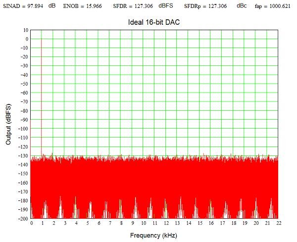
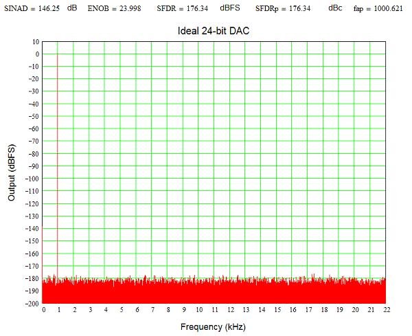
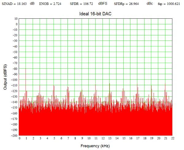
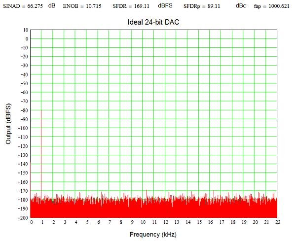
Here are some pictures showing the effects of bit reduction. I started with a 16-bit DAC, then simulated a 24-bit DAC, then rounded the 24-bit output to 16 bits, and finally truncated the results to 16-bits. The last is similar to what I would expect improper sign extension would do.

The ideal 16-bit and 24-bit outputs:
Figure 1..JPG
Figure 2..JPG

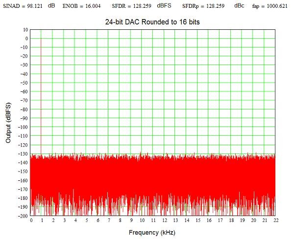
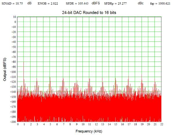
Now take the 24-bit data and round to 16 bits, effectively creating a 16-bit DAC output. This is the sort of thing one would expect if the lsb extension is handled properly.
Figure 3..JPG

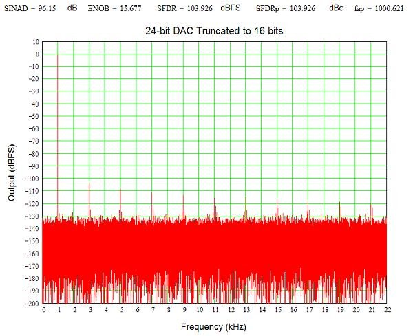
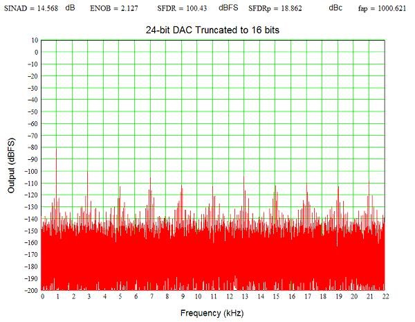
Now let's emulate incorrect sign extension by truncating the 24-bit data to 16 bits. This is the same as setting the bottom 8 bits of the 24-bit data to 0, the problem described in the paper Nick cited. Note the harmonics added as a result of truncation. They are certainly mathematically significant, but as far as hearing spurs more than 100 dB down, well, probably take better ears than mine.
Figure 4..JPG
 

DonH50

Member Sponsor & WBF Technical Expert
Jun 22, 2010
3,952
312
1,670
Monument, CO
One more set of pictures, this time with the signal 80 dB below full-scale (maximum). These show the effect of quantization on small signals even on an ideal converter. The ideal 16-bit now has a number of harmonic spurs since we have reduced the signal to using only about 3 bits. The ideal 24-bit does not have all those spurs since the signal still has about 10-bit resolution even at -80 dBFS.

Figure 5..JPG
Figure 6..JPG

Rounding the 24-bit data to 16 bits we see the same sort of harmonics seen in the ideal 16-bit converter as expected.

Figure 7..JPG

Truncating the 24-bit data to 16 bits we do increase the distortion slightly, but it is already large enough that it is hard to tell.

Figure 8..JPG


Conclusion: Truncation, or improper sign extension, can indeed produce significant errors. However, while mathematically significant, in this case the distortion is probably not audible.

YMMV - Don
 

Nicholas Bedworth

WBF Founding Member
May 7, 2010
312
0
0
Maui, where else?
Don...

Fascinating! So the result of improper LSB extension is certainly measureable, and few or no spurs are always better, so the issue is, firstly, whether such artefacts are audibile if they "survive" all the way through the DAC process, and secondly, a related question, do the spurs cause certain DAC architectures and methods more problems than others?

Looks like the truncation process adds about 10 dB to some of the spurs. Would it be easy to integrate the difference between the rounded and clobbered methods?

Truncation is easy enough to understand, one just clobbers the bits. (BTW are you doing the clobbering only for the negative values?)

Now, could you explain the rounding process? Is this another term for dithering?

This is where it might get really "exciting", namely if the spurs create trouble with some process. Presumably anything that increases the state variable noise in unnatural ways, isn't going to be helpful. Martin and Dustin gave a superb seminar at RMAF last year, and they explained a great deal about how their approach works: see http://www.esstech.com/PDF/sabrewp.pdf

Good work!

Nick
 

RayCtech

New Member
Apr 17, 2012
8
0
0
Multiple..
Don...

There is several issues with your previous posts that I would like to comment.

1. The "paper" you have read treats the "data" as a DAC would have done it.
For 16 bit two´s complement code there is a sign bit (MSB) and 15 bit positive or negative levels.
Thus you are not correct when you say that the largest LSB error can be:
At full-scale, the lsb is only 1/65,535th (-96 dB) of the signal
The correct would be 1/32768 (-90 dB) if it was straight binary numbers,
but as it is two´s complement code the MSB is also a value and are inverted before it is summed with the remaining 15 bits.
This is done to allow a DAC to have a midpoint that are "zero",
but it also have the effect of reducing the output level by a additional 6 dB...
The "paper" you refer to do a calculation from the two´s complement code numbers and calculates the real "analog" values out of a "perfect" DAC,
and then compares the LSB extension corrected values with the values without the LSB extension.
The two´s complement code numbers are also treated as two´s complement code numbers..

As I see your simulations they are simulating binary data and not two´s complement code numbers...
And I am not sure how the simulations "simulates" a real DAC.

2. The error / distortion that are calculated (in the "paper") are done with the actual signal / signal level as reference,
and not as you have done with full clipping level / 0 dB as reference.

It is the real distortion of the signal that are interesting and relevant.
In real music recordings like a classical record the level will in periods be several tens of dB down from clipping.
In addition will most acoustical recordings have the recorded levels falling with frequency,
and are down maybe 20 - 40dB at the highest frequencies.
Thus the LSB extension error will be easily audible and affect most music with some kind of dynamic span.

In your example of a -80 dB signal the distortion is only -20 dB down from this signal and not -100 dB as you have stated (-100 dB down from clipping).
The harmonics must also be summed to get the total THD and then the numbers get much worse,
but these simulations does not only show the LSB extension error, but also the two´s complement code format error.
And there is the question in what references and what kind of number formats that are used.
If this had been a 30Hz bass tone the distortion level would have been more audible then the original tone...

What the simulations show are that there IS an effect of the LSB extension correction.

Do you have any possibility to do the simulations with implications I have mentioned ?

Ray
 

DonH50

Member Sponsor & WBF Technical Expert
Jun 22, 2010
3,952
312
1,670
Monument, CO
Hi Ray,

I don't think we disagree, just represent things a little differently. I have designed DACs, and ADCs, but most of my career has been with high-frequency data converters, that is 500 MS/s to 10 GS/s or more. They were (with very few exceptions) straight binary, not two's-complement, so were real to me (and my customers). I have little experience with audio DACs though of course the principles are the same. I have designed a variety of ADC architectures, including flash, folded-flash, parallel SAR, dual-slope and integrating, and delta-sigma. DACs have been segmented conventional and delta-sigma. Most of the delta-sigma loops used very high speed CT modulators. So, I can claim some ADC/DAC expertise, but little to do with audio.

Even for a two's-complement DAC an lsb is simply one unit out of the maximum. However, I see your point; you are treating the lsb error as one part of one-half the signal. I always reference to full-scale, peak-to-peak. The error is 1/32768'ish for just the negative half of the signal, but assuming signals go positive and negative about the center I think it should still be reference to 65,536? What am I missing?

I also do not see how it reduces the signal by 6 dB. However you represent them, there are still 65,536 individual steps; you are not reducing the DAC's resolution by changing the input number format. Instead of 0 to 65,536 you go -32,768 to +32,767.

My simulation does not care the number format; it creates a sine wave (or waves, or other signals) and converts them. For these simulations I modeled a simple unary DAC as it was faster and easier than more complex architectures. Since we are looking at the effect of lsb extension on an ideal DAC, the actual DAC's topology does not matter.

The plots several metrics above the plots. I calculated absolute SINAD which does scale with signal, ENOB which is obvious, SFDR referenced to full-scale (dBFS), and SFDRp references the signal level (carrier, dBc). The program I grabbed for this did not have my library calls for THD and such. I was trying to get something done since I promised Nick a week or two ago and since then got caught up a in a 24/7 work project (I will be heading in shortly, ad yes it's Sunday, argh!) Note that THD does not make the numbers worse, it simply provides an additional metric. And yes, the sum of all errors is worse than any single one...

As for real levels, well, I assume they go from very small to near full-scale. I figured -80 dBFS was a reasonable bound to show the effects quantization has on small signals. That allows 20 dB headroom above a nominal maximum average signal level, and 60 dB below. More dynamic range than a record, probably in the ballpark for a CD, probably a little less than the max in a movie. It is an arbitrary choice and I am sure there are plenty of recordings of all types with higher (and lower) dynamic range.

What I wanted to show was that you are only using about 3 effective bits out of 16 when you are 80 dB below full-scale with a 16-bit DAC. Once you do lsb extension, properly or not in whatever format, you have lost all information below the 16-bit level. You effectively turn your 24-bit DAC into a 16-bit DAC. The rising distortion with reduced signals is a function of have finite resolution, not improper lsb extension. That said, messing up the sign extension clearly makes it a little worse. In my example, it cost about 1/2 a bit (ENOB) and a little over 3 dB in SINAD (signal to noise and distortion). So, yes, it is significant. I am not sure it is audible, but you are right I referencing full-scale. If you turn up the volume so that -80 dBFS signal is clearly audible, you will hear the noise and distortion. Just be sure to turn the volume down before a louder signal comes along! The nasty spurs quantization generates at low levels is one reason dither is used in virtually all audio converters today.

Yes, I agree high-frequency signals have much lower amplitudes in general, but of course we are also less sensitive to them. At least I am, at my age (50+ and getting plus'er :) ). I could have done a multi-tone or noise test but figured the best way to see the impact was with a single tone. I chose 1 kHz as a typical reference tone.

"If this had been a 30Hz bass tone the distortion level would have been more audible then the original tone..." Because the harmonics are more audible to human hearing than the fundamental? Agreed.

***

Hi Nick,

Yup, the effect is most certainly measurable. I only wonder how audible it is. Since I don't have test tones nor a perfect DAC I cannot say. It is pretty low-level, and even the loss with a small signal input appears to me to be pretty much covered by "conventional" quantization noise. But,the whole issue of quantization errors at low levels is a subject of endless debate. I just wanted to show the impact.

Rounding is one of the simpler methods of sign extension and simply rounds the number the same way you would round 1.678 to 1.7 or -11.225 to -11.2. In this case we are rounding numbers with a range of roughly +/-8,388,608 (24 bits) to +/-32,768 (16 bits). Rounding effectively keeps the lsb correct so you get the same result as if you used a "perfect" 16-bit DAC, i.e. only 16 bits of our perfect 24-bit DAC.

Truncation chops off all the extra bits, replacing them with 0's, no matter the sign or what the extended lsb bits should be (1's or 0's). This is what the error appears to do, though it is working on two's-complement numbers as Ray notes. However, I would expect the impact to be the same or very similar. I did not have a two's-complement representation in my program as Ray points out but argue the effect is the same or very nearly so. It cannot be more than an lsb off mathematically.

Dithering is something else entirely. When some one "dithers" they cannot make up their mind, vacillating between two or more positions. We add noise to our DACs at around the lsb level to make the lsb transitions more random. This produces a noise floor that is more white, that is higher but flatter", than the discrete spurs produced by ideal quantization. This provides a more pleasing, analog-like noise floor, especially noticeable with low-level signals.

Gotta' run, HTH - Don
 

DonH50

Member Sponsor & WBF Technical Expert
Jun 22, 2010
3,952
312
1,670
Monument, CO
Sorry Nick, you asked:

"So the result of improper LSB extension is certainly measureable, and few or no spurs are always better, so the issue is, firstly, whether such artefacts are audibile if they "survive" all the way through the DAC process, and secondly, a related question, do the spurs cause certain DAC architectures and methods more problems than others?"

The spurs will survive; the antia-alias filter does nt touch them since they are in-band (well below the HF cut-off). Harmonic (and intermodulation) spurs are more audible than noise, and in my example odd-order products are generated with no even-order terms meaning a raspy, buzzing sound instead of a milder buzz.

Any ideal DAC of any architecure generates the same spurs. Different architectures do create spurs differently, yes, but that is beyond the scope of this, or at least the time I have this morning... As for "handling" them, I am not sure what that means. The spurs come from sampling theory.
 
Last edited:

Nicholas Bedworth

WBF Founding Member
May 7, 2010
312
0
0
Maui, where else?
Don,

Thanks for the constructive dialogue and experimental findings... Note how a "simple" effect gets quite complex when we examine all the details. By "handling", my meaning was that the ESS type DACs do things completely differently "inside" than, say, an MSB-style ladder DAC. So it occurred to me that the issue that Ray is raising here might be especially problematic for the ESS DACs where they have elaborate signal processing to reduce state variable noise and so on.

When the current "real work" crisis subsides, it will be great to hear your further thoughts.

And thanks to Ray for his additional clarification and comments. The idea here is to tease apart the various issues and their consequences, so that we can have a coherent and thorough understanding of how bad the problem is, and its effects in the audio domain.

Don... perhaps next weekend, if they let you out of work for Sunday dinner :) perhaps you can do some simulations with the THD, that will be quite interesting. All those spurs probably add up to a lot of crud. And if you can use test stimuli that are more 1/f that will be a step closer to music than our trusty 1 kHz test tone.

Good work, guys!

Nick
 

DonH50

Member Sponsor & WBF Technical Expert
Jun 22, 2010
3,952
312
1,670
Monument, CO
What is an "ESS" DAC?

Have a few minutes, so here are a few terms and discussion:

THD = Total Harmonic Distortion = sqrt(sum(harmonics^2)): Essentially the "sum" of all the harmonic distortion terms relative to the fundamental. For a 1 kHz signal, the harmonics occur at the integer multiples of the signal frequency, 1x, 2x, 3x, and so forth. The harmonics of a 1 kHz signal are 2 kHz (2nd harmonic), 3 kHz (3rd harmonic), etc. Most measurements use the first 10 harmonics to define THD (above that the contributions are usually very small and can be neglected without changing the result).

SNR = Signal-to-Noise Ratio: Ratio of signal level (voltage, current, power, whatever) to noise. The noise is all the noise integrated (summed, added-up) over the system bandwidth, that is the "total" noise. Data converters create their own quantization noise because they quantize the signal (chop it into discrete steps in time and amplitude) in addition to wide-band thermal, shot, and other "analog" noise sources. Some manufacturers include distortion in the SNR, some don't. The definition implies only the fundamental signal and noise. The IEEE (Institute of Electrical and Electronic Engineers, a worldwide organization that sets many standards, including those for characterizing ADCs and DACs) has e-emphasized SNR because it is sometimes mis-used.

SINAD = Signal-to-Noise-And-Distortion: This compares the signal to everything else whether it be distortion (THD, IMD, whatever) or noise (thermal, shot, flicker, quantization, whatever). It is a more stringent criteria than THD or SNR and is actually easier to determine since you compare the signal to everything else. No having to separate out harmonic terms and such; THD, IMD, all noise, any other errors are reflected in the SINAD (SINAD "includes" THD, IMD, etc.) This is what the IEEE uses (and thus so do I).

ENOB = Effective Number of Bits: A way to see how many "real" bits we get out of the converter. ENOB is derived from SINAD as roughly (SINAD - 1.8) / 6 dB.

SFDR = Spurious-Free Dynamic Range: The ratio of the signal to the highest spurious term (peak spur). For data converters we often provide two measurements, one referenced to the converter's full-scale (FS) output, dBFS, and the second referenced to signal ("carrier" from old radio days, dBc).

I use SINAD, ENOB, and SFDR almost exclusively, with their definitions and characterization methods defined in the IEEE's ADC Standard. In my radar/lidar/elint/communications world THD does not really matter since any spur is a problem, which also means SNR itself is not often relevant.

When Ray discusses high levels of distortion for small signals he is quite right, but remember this is high distortion on a very small signal. I am not sure I could hear 3% distortion on a signal 80 dB down; I'm not sure I could even hear the signal that quiet! But, a valid counter is that we often record with substantial headroom to eliminate (or at least greatly reduce) clipping the ADC. If the loudest average level is set to 0 dB, we probably allow 20 - 30 dB headroom above that, thus the 96 dB dynamic range ('ish, I won't get into the SINAD/SNR/SFDR issue here) of our perfect 16-bit DAC is reduced to 66 - 76 dB. A signal 80 dB below full-scale is thus 50 - 60 dB below our reference average loud signal. At that level, we are only toggling 3 bits out of 16. A perfect 3-bit converter only has about 18 dB dynamic range, so yes the noise and distortion relative to the signal is much larger. Just don't forget the signal is much smaller, too...

Then we add the lsb extension error and indeed things get worse. Audibly? I don't know. I expect the debate will rage on, but hopefully this has helped people understand what and why.

BTW, I created these results with a mathematical model using a program called Mathcad. That way I could use a well-defined system and "perfect" DAC to which I added known errors. A real DAC would add it's own errors (distortion) and noise, as would anything else in the signal chain (analog output buffers, measuring system input buffers, etc.)

HTH - Don
 

DonH50

Member Sponsor & WBF Technical Expert
Jun 22, 2010
3,952
312
1,670
Monument, CO
A quick look at the ESS site does not make clear their architecture, save it is oversampled (does not mean it is delta-sigma) and uses dynamic matching (good idea but not that uncommon) to reduce errors. Anyone have their patent? Not all that relevant to this thread, just curious...
 

DonH50

Member Sponsor & WBF Technical Expert
Jun 22, 2010
3,952
312
1,670
Monument, CO
Still have not had tiome to read it... :( It appears to be delta-sigma based with interleaving. There are some interesting wideband delta-sigma approaches using Hadamard sequences and such (I explored a few for an advanced design project in my previous life).
 

Nicholas Bedworth

WBF Founding Member
May 7, 2010
312
0
0
Maui, where else?
Yes, and the ESS guys are really, really smart. The delta-sigma is really not the point in their products, it's more the signal processing that allows them to greatly reduce jitter, state variable noise and all those interesting things.
 

RayCtech

New Member
Apr 17, 2012
8
0
0
Multiple..
Some new and revised informations regarding the "I2S and 16 to 24 and 32 bit conversion LSB extension errors":

When music data in 16 bit two´s complement format is sent to devices with 24 or 32 bit depth the data must be LSB extended to the required bit depth.
This is also true for any music data like 24 bit as long as the source bit depth is lower than the destination bit depth.

The I2S «standard» states that 0 padding should be used for both positive and negative samples.
This method is creating an error for negative samples that varies with the inverse of the signal level-
For 0 dB FS (16 bit) (maximum level) the error is ca. 0.0035% and for a minimum signal level (1 bit signal) close to 100%.

It would have been more correct to conditionally LSB extend- «0» padding for positive samples and «1» for negative as this would have corrected the error for the negative samples,
but due to the ´two´s complement format error´ this conditional correction method will create its own errors..

This «combination effect» was discovered this when re-checking and re-calculating the conditional LSB extension method to provide updated data for the LSB extension white paper.

A proprietary method was invented that both allows for correct LSB extension and also correction of the ´two´s complement format error´- and is included directly into the discrete DAC128 state machine a DAC I now are finishing. This result in a output that is free of both the LSB extension error / distortion and the bipolar offset error normally created as a result of the ´two´s complement format error´, and also the "combination error" that will be created if corrections is not implemented correctly.

This solution was selected after extensive analysis of where and how the LSB extension errors and the ´two´s complement format error´ can / will occur and the effects it causes.

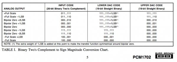
The bipolar offset caused by the ´two´s complement format error´ that causes a asymmetrical transfer function around bipolar zero have been addressed in many DAC designs - here a attachment showing how it was done in the PCM1702 DAC chips:
BB PCM1702.jpg

As a result of these findings the conditional LSB extension method as previously described should NOT be used directly without also implementing a correction of the ´two´s complement format error´...

Here is the simplest and gravest error the conditional LSB extension method will cause if used without the ´two´s complement format error´ correction routine:

The value -1 cannot be conditionally LSB extended due to the new value will still be -1.
Here shown with -1 and +1 to make it easy to "view":

A negative 16 bit value of -1:
1111111111111111 = -1
Extended "normally" to 32 bit:
11111111111111110000000000000000 = -65536
Extended "conditionally" to 32 bit:
11111111111111111111111111111111 = -1

A positive 16 bit value of 1:
0000000000000001 = 1
Extended "normally" to 32 bit:
00000000000000010000000000000000 = 65536
Extended "conditionally" to 32 bit:
00000000000000010000000000000000 = 65536

Regardless of what bit depth -1 is extended to the result will continue to be -1 with conditional extension...

More information regarding the combined "conditional LSB extension and the ´two´s complement format error´ routine" will be published when the white paper regarding this is finished.

In addition to the proprietary method (hardware) implemented and used for correct LSB extension and also correction of the ´two´s complement format error´- in the discrete DAC128 state machine in my DAC- I am also working on a software implementation that can be used together with other existing DAC chips.
 

DonH50

Member Sponsor & WBF Technical Expert
Jun 22, 2010
3,952
312
1,670
Monument, CO
On the average the error on the lsb is 50%. Even if it were 100%, and for certain samples and converter architectures it may be, that's an error of 1 part in 65,536 for a 16-bit DAC, still 96 dB below full-scale, so I am not at all sure it is audible. It's kind of like dithering the noise floor. Which all delta-sigma designs do anyway so would mask this error.
 

About us

  • What’s Best Forum is THE forum for high end audio, product reviews, advice and sharing experiences on the best of everything else. This is THE place where audiophiles and audio companies discuss vintage, contemporary and new audio products, music servers, music streamers, computer audio, digital-to-analog converters, turntables, phono stages, cartridges, reel-to-reel tape machines, speakers, headphones and tube and solid-state amplification. Founded in 2010 What’s Best Forum invites intelligent and courteous people of all interests and backgrounds to describe and discuss the best of everything. From beginners to life-long hobbyists to industry professionals, we enjoy learning about new things and meeting new people, and participating in spirited debates.

Quick Navigation

User Menu

Steve Williams
Site Founder | Site Owner | Administrator
Ron Resnick
Site Co-Owner | Administrator
Julian (The Fixer)
Website Build | Marketing Managersing