Taking the OTL VT Concept to the Next Level: NO Transformers

Mark (Basspig) Weiss

Well-Known Member
Aug 3, 2010
682
37
940
New Milford, CT
www.basspig.com
Back in the '60s, I built an OTL with 8020 triodes. It produced a modest 25 watts into 16? loads.

After many years of tubes, then building the ultimate audio system over a 38 year period, I am back to tinkering for pure pleasure in the lab. So my fascination with OTL VT amps resurfaced after a long slumber, and I've started a new project, on a bigger scale and more radical design approach.

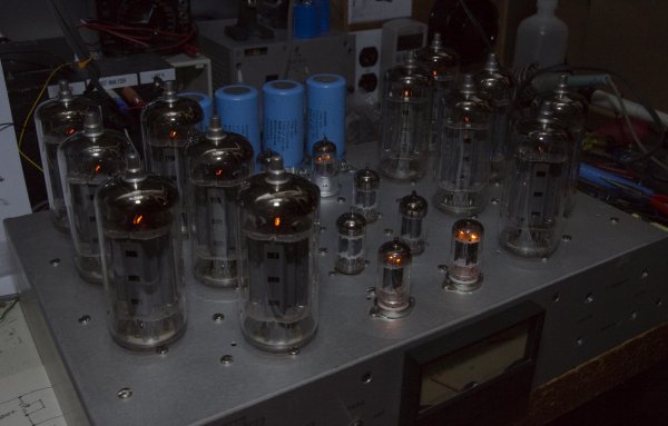
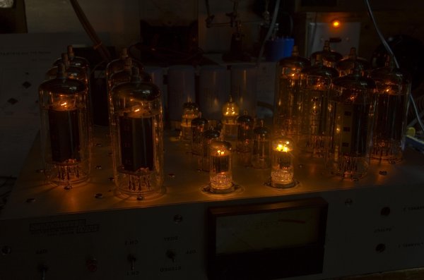
To wit, here's a photo of the early construction phase. Here we see a stereo amplifier. The right channel fully populated with Beam Tetrodes. The amp topology employs 12 Beam Tetrodes and 8 dual triodes.
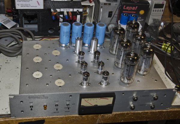

NIK_8696.jpg


Output topology is loosely based on Circlotron designs. It is a self-balancing, DC coupled circuit. The challenge I've undertaken in this amplifier is to have it totally DC coupled from input to output. This requires multiple floating power supplies.

In this design, I'm using Schottky fast recovery diodes with 35 amp capacity for the output tubes. You might say that sounds like a lot of current, but these tubes are quite different. Instead of 6800? plate resistance, we are talking about 80? plate resistance. Even lower, with a circuit to modulate the screen grids with the audio signal, in addition to the control grids, greatly increasing peak power handling and current. The particular tubes can draw up to 1800mA of plate current at 175V DC. Six of these tubes per channel should provide a conservative 150 watts from DC to 500KHz.

Particular attention must be paid to the driver and phase inverter, given the grid damping when the outputs are driven to full power. A 5687 was chosen for the Split Cathodyne phase inverter, due to it's high transconductance and ability to drive lower impedance loads. Circuitry will be balanced nearly all the way to the input, and maybe all the way, if I need to have common mode rejection to isolate the ground from other equipment (you see, this amplifier has NO transformers in it and connects direct to the AC mains).

Solving the filament powering was another challenge. My approach is to use a TRIAC with filtering, followed by a bridge rectifier and DC smoothing capacitor. The filaments are in a series string, using 76 volts at 2.5 amps. The smaller tubes are in series too, using 96 volts at 150mA. These will be powered off a separate DC supply.

Making the amp totally transformerless brings many challenges with it. One is to design a truly floating input that has high CMRR. Another is keeping TRIAC switching noise out of the audio. These and other engineering challenges await, as I continue to build this amplifier. But with no transformers to limit current, this amplifier should have ample reserve of power delivering ability, over a wide and flat frequency response. I hope to have it perfected by next March, in time for the 2nd Annual B.A.S.S Meeting.
 

amirm

Banned
Apr 2, 2010
15,813
38
0
Seattle, WA
When you said transformerless I thought you just meant output, not the elimination of the power supply! Quite clever if you can get it working. Pls keep us posted!
 

DonH50

Member Sponsor & WBF Technical Expert
Jun 22, 2010
3,952
312
1,670
Monument, CO
That looks very cool!

What are the output tubes?

Why use triacs? I confess I cannot think why they would be better than some other off-line supply approaches... Except there are plenty of high-voltage triacs around.

I have built a few fully direct-coupled tube circuits and they were a pain. Never tried to eliminate the power supply transformers, however; that's a big step! I used a bunch of regulators to stabilize things, along with various CM loops and an output dc-sensing circuit to save the speakers if a tube arced. I piddled with several output tubes, include the venerable 6550, EL34, 6146, and a few others (most ambitious was a 3 kW transmitter tube used for modulators and RF outputs in big commercial transmitters). I found I needed lots of parallel tubes to get the current drive needed so actual power output became secondary. At the end of the day, my best design was panned for being "too solid-state sounding". I gave up...
 

Mark (Basspig) Weiss

Well-Known Member
Aug 3, 2010
682
37
940
New Milford, CT
www.basspig.com
I spent 20 minutes writing my reply, and for some reason, the system 'ate' it and said I was posting a blank. Hit the back button, but the editor was gone... oh well, I'm not going to rewrite everything..
\
Highlights; output tubes are Russian 6P45 (US equiv 6KG6.)
TRIACs to avoid dumping thousands of BTUs in resistive loss while shedding 45 volts.
Looked at transmitting tubes but cost, voltages, impedance and ergonomics were not favorable.

The other 19 minutes of writing you'll have to guess at. I'm tired and it's late.
 

DonH50

Member Sponsor & WBF Technical Expert
Jun 22, 2010
3,952
312
1,670
Monument, CO
Thanks. I have lost count of how many times I have lost a long post due to a glitch, either the PC, the network, or me just hitting the wrong button and it all goes bye-bye. I then copy the window frequently, or even write in Notepad or something, but soon forget/get lazy and do it again...

6KG6 sounds real familiar -- guitar amp tubes, or maybe TV sweep tubes?

I understood the idea of triacs for reducing loss, just wasn't sure why you didn't use IGFETs or something. Not really relevant anyway.

My experience with transmit tubes was "less than ideal" (sounds better than "a failure"). They are largely designed to handle thousands of volts to keep current flow reasonable so it's a tough impedance matching problem, and building 10 - 100 A floating filament supplies is a pain. I actually had a 10 kW tube sitting on a bench at one time, but ultimately never built anything with it.

Impressive achievement, Mark! Wish I had more time for DIY; I keep thinking I want to get back to that someday, but for now when I get home I just want to eat and relax.
 

mep

Member Sponsor & WBF Founding Member
Apr 20, 2010
9,481
17
0
Having no power transformer is extremely dangerous. If you don't use a polarized plug and plug it in the wrong way, you will have 120v on the chassis. Even if you do use a polarized plug but don't wire it correctly (or if your house wiring isn't wired correctly to the outlet), you will have 120v on the chassis. It's a cheapskate way to build an amp, but it is a dangerous way to build an amp.
 

DonH50

Member Sponsor & WBF Technical Expert
Jun 22, 2010
3,952
312
1,670
Monument, CO
Actually, a lot of cheap components (and some pretty expensive ones) use simple off-line supplies with no transformer. But yeah it can certainly be dangerous if done wrong! The catch with an amp is that a lot of off-line supplies float the circuit and the chassis is grounded (has to be to meet code). That's not a problem for a little clock or radio, but a problem for an amplfier. It's not just the chassis that must be isolated; you really don't want the speakers floating on the ac line...
 

Mark (Basspig) Weiss

Well-Known Member
Aug 3, 2010
682
37
940
New Milford, CT
www.basspig.com
As this is an experimental challenge, not a commercial product, I'm not too concerned with the direct line power supply issues. I don't even think it's possible to get UL listed with such a configuration.

My approach to dealing with this is more along the lines of protecting source devices. A high CMRR input differential stage, where common and hot are both floating and not at chassis potential.

To protect the chassis, yes, it will be grounded on a 3 prong line cord. If plugged into an incorrectly wired outlet, the 'hot' neutral will be shorted to ground through the line fuse. A blown fuse will be the result. Of course, if the outlet is missing ground, or if the ground is wired to hot, well, the building owner has more serious problems than an amplifier!

These tubes are sweep tubes, that is correct. Cheap, VERY low plate resistance, very high transconductance, and plate currents up to 1800mA at 170 V B+, according to the Russian data sheet I have here.


I'm dead tired. Long day working on the house, then repairing a microwave studio to transmitter link receiver, which was all SMD components. The parts I had to replace were the size of a head of a pin and I only had a conventional pencil soldering iron to do the work. Repair was successful though--200uV of signal now gives 200uV of reading and receiver sensitivity now correctly matches the input signal, about 20 orders of magnitude better than it was when it arrived here this evening. My eyes need a rest!
 

FrantzM

Member Sponsor & WBF Founding Member
Apr 20, 2010
6,455
29
405
Mark

I understand the proof-of-concept desire and that is fine. What I fail t understand is the advantage that such a product would bring in. Could you elaborate on the (theoretical) advantages, if any?
 

DonH50

Member Sponsor & WBF Technical Expert
Jun 22, 2010
3,952
312
1,670
Monument, CO
Not Mark but for some off-the-cuff thoughts of the pros:

No output transfomer
  • Less size and weight
  • Direct coupling could improve bandwidth and damping factor
  • Potentially lower distortion (no transformer hysteresis)
  • Potentially no coupling capacitors (not sure if Mark implemented direct coupling everywhere; I have done that and it is a lot of work for marginal but measurable gain)
  • Less power/heat wasted in the transformer

No power transformer
  • Less size and weight
  • Less heat due to higher efficiency
  • Less wasted power also due to higher efficiency (assuming a switching design)
  • Potentially lower noise due to lower coupled LF EMF fields (though could be higher if switching noise not suppressed/filter)

Mark can add to this...

HTH - Don
 

Mark (Basspig) Weiss

Well-Known Member
Aug 3, 2010
682
37
940
New Milford, CT
www.basspig.com
Metcal, Mark...

Thanks Don. Will check that out if not too pricey. I may see more of this SMD stuff.. the guy is sending me another MARTI that also has the same low sensitivity problem, given I've fixed this one.
 

Mark (Basspig) Weiss

Well-Known Member
Aug 3, 2010
682
37
940
New Milford, CT
www.basspig.com
Don pretty much nailed all the advantages. Of course, reduced size, weight and cost are others. Also, no transformer to produce sags in voltage (unless you want 100lbs of iron there) when the amp is under load. The entire amp weighs less than 10lbs. It's just an aluminum chassis, tubes, wiring and components. This was part of my challenge: to make quite possibly the world's lightest weight per watt VT amplifier.
 

DonH50

Member Sponsor & WBF Technical Expert
Jun 22, 2010
3,952
312
1,670
Monument, CO
Thanks Don. Will check that out if not too pricey. I may see more of this SMD stuff.. the guy is sending me another MARTI that also has the same low sensitivity problem, given I've fixed this one.

The Metcal stations are very nice but expensive for an individual (~$1500+ last time I checked, several years agao). Another company makes similar units but cheaper (forgot the name but it is one of the usual suspects). Less expensive is a Weller (or whatever) controlled-temperature iron with a selection of special tips for SMD rework; that is most practical for an individual IME. Best (arguably) and most expensive are the hot-air rework stations.
 

Mark (Basspig) Weiss

Well-Known Member
Aug 3, 2010
682
37
940
New Milford, CT
www.basspig.com
The Metcal stations are very nice but expensive for an individual (~$1500+ last time I checked, several years agao). Another company makes similar units but cheaper (forgot the name but it is one of the usual suspects). Less expensive is a Weller (or whatever) controlled-temperature iron with a selection of special tips for SMD rework; that is most practical for an individual IME. Best (arguably) and most expensive are the hot-air rework stations.

I was looking at a set of nozzles http://www.ebay.com/itm/38046395379...XX:IT&_trksid=p3984.m1436.l2649#ht_2235wt_889 like these.

I did those last repairs with a 1960s-vintage Ungar soldering iron with the standard flat bladed tip. Ugh.
 

DonH50

Member Sponsor & WBF Technical Expert
Jun 22, 2010
3,952
312
1,670
Monument, CO
What do those nozzles go to? If an airflow rework station, they won't help you...

Weller and Ungar have new models that allow you to use tips similar to the "nozzles" shown in the sale you linked. I'd be very nervous about using my old (70's vintage; my first one died) iron on SMD. The components and boards are more sensitive to heat damage (don't ask how I know this but you can guess ;) ); I much prefer a temperature-controlled iron. I keep thinking I should pick up a nice unit, but rarely need to solder at home and any fine stuff I just take to work where we have all the tools and toys. Including stereo 'scopes so I can see the specks of dust SMD 0402/0201 look like to me...

I have taken a file to the tips on my old iron with a 25W heater (has 25, 40, 52W -- no idea the reasoning behind the spread) for SMD stuff but it is an exercise in frustration. Proper tool for the job and all that...
 

Mark (Basspig) Weiss

Well-Known Member
Aug 3, 2010
682
37
940
New Milford, CT
www.basspig.com
Definitely, the right tool is the best option. I mainly work on vintage gear, so SMD is a once in a blue moon affair, but if I see more SMD on a regular basis and more modern gear coming in for repair, I'll have to consider a dedicated workstation.

Right now, my goal is to get the shop busy. My target is five amplifier repairs per day. At an average of $200 each, that would be a living wage and my wife won't have to look for a second min wage job to supplement the one she works now. I'm currently at about 1 amp a week. Going to scout some music stores and let em know I can service their customers' amps and see where that goes.
 

Mark (Basspig) Weiss

Well-Known Member
Aug 3, 2010
682
37
940
New Milford, CT
www.basspig.com
Filament Power Test

Got the other half of the set of 6P45s this week from Russia. Now I can test my series string. Using TRIAC circuits to shed the extra voltage without big honkin' high power resistors. Still needs refining, but beginning to see the light!


NIK_8705.jpg

NIK_8715.jpg
 

DonH50

Member Sponsor & WBF Technical Expert
Jun 22, 2010
3,952
312
1,670
Monument, CO
Are you doing anything to balance the filaments in your string? Any idea of the variations tube-to-tube? That used to be an issue for me so I got away from series connecting the filaments. Without transformers, tricky...

p.s. Just saw Myles' pix of the new ARC monster amp, now your glow-in-the-dark amp, gotta' quit these threads as I'm getting the tube itch again!
 

Mark (Basspig) Weiss

Well-Known Member
Aug 3, 2010
682
37
940
New Milford, CT
www.basspig.com
At some point, that is a lesser priority on my to do list, but I plan to trim the filament branches with resistor values across tubes with higher than average voltages present. The big challenge right now is filtering out TRIAC switching noise and keeping it out of the low level stages.
Another interesting challenge is powering this whole thing.. 1400ma per tube, 12 tubes at 170 volts--that's over 3000 watts. I see why big tube amps are usually built as mono blocks or 3-phase powered.
It took me over forty years to get re-inspired to build another tube amplifier. I'd built countless Williamson-like amps with transformers, all limited in power and bandwidth, but had built one OTL in the early '60s with 8020 triodes that put out maybe 25 watts in to 16?. But this time, I want to eliminate all transformers. That saves about $4000 off the cost of building the amp.
 

About us

  • What’s Best Forum is THE forum for high end audio, product reviews, advice and sharing experiences on the best of everything else. This is THE place where audiophiles and audio companies discuss vintage, contemporary and new audio products, music servers, music streamers, computer audio, digital-to-analog converters, turntables, phono stages, cartridges, reel-to-reel tape machines, speakers, headphones and tube and solid-state amplification. Founded in 2010 What’s Best Forum invites intelligent and courteous people of all interests and backgrounds to describe and discuss the best of everything. From beginners to life-long hobbyists to industry professionals, we enjoy learning about new things and meeting new people, and participating in spirited debates.

Quick Navigation

User Menu

Steve Williams
Site Founder | Site Owner | Administrator
Ron Resnick
Site Co-Owner | Administrator
Julian (The Fixer)
Website Build | Marketing Managersing