Hi Mark
While it would be a sign of a big problem in electronics, not being able to reproduce the input waveshape of a complex signal (like a square wave) is not an expectation with home loudspeakers, particularly if they have more than one driver in play.
Also, like many subjects there are at least two ways to look at it. For example, the person who lives in theory will say to produce a sq wave requires a bandwidth DC to light and if one considers the math, that is how it looks.
A person who works with electronics will also suggest that on an oscilloscope, that one can get a “perfect” looking square wave with bandwidth extending from 1/10 to 10X the center frequency.
Like looking for an asymptote point, there is the practical and theoretical requirement.
Why is this “hard’ for a loudspeaker?
In the late 70’s Dick Heyser wrote a number of papers, the first to identify a loudspeakers acoustic phase. He suggested that one can consider a loudspeaker’s acoustic phase as something like it’s origin (in time) moving forward and back with frequency. He also developed the first way to measure acoustic phase the TDS or TEF machine.
To preserve / reproduce a square wave (by eye) one needs a large space above and below where the amplitude and time do not change, all the important harmonics have to emerge at the same time.
Loudspeakers on the other hand spread signals out in time, they have an all pass response, when you go to a multi-way system that spread in time from high to low is generally greater still.
It is asserted that this kind of time error can’t be heard (with headphones) and so it is ignored.
In 1980, the company I worked for got a TDS machine and B&K mic for me to use. Being a loudspeaker fan and having just started developing the Servodrive woofers I measured everything I could even non-loudspeaker stuff. Eventually I was presenting the goofey stuff at TDS seminars and was then asked to measure the Great Pyramid in Egypt (if curious here is a story about that)
http://www.livesoundint.com/archives/2000/julyaug/pyramid/pyramid.php
I had been collecting horns and drivers for some years with the thought that someday I would build a large horn system for my home as they would have the peak capacity none of my home built electrostatics had. . The inspiration was the jbl375 and big len’s I had accumulated. These, by measure were essentially “perfect” through the mid band, the problem was I could not see any way to make them part of a system because of the spacing between them and what they mated to.
Working on acoustic levitation sources, it was clear to me there was a fundamental difference between how sources acted when they were less than a quarter wavelength apart and more than that. Closer, the sources added coherently into one source, much greater and the sources do not add coherently and produce an interference pattern.
At wavelength differences, reversing the drive to one source causes NO change in radiated power, only the shape of the interference pattern changes so at best most crossovers are concerned with the on axis lobe only.
I did not see any way to add the ranges in a multi-way that they did not interfere acoustically and over the years I had a good stock of parts but no solution..
So far as a square wave, there had been only three loudspeakers that I knew of first hand that could reproduce a square wave unilaterally. By that I mean that usually one can find a combination of frequency and mic position where one see’s a square wave but if you change anything, it is lost.. This is especially true in multiway systems where the change in paths with position are measurable physically and acoustically.
In your test, unless you had highly directional speakers, one would have a lot of room arriving at the LP.
If one were close enough for the direct to swamp the reflected sound, or outdoors then one could more reliably see what the speaker really does.
The commercial speakers were an 8 inch full range JBL driver above the lower mid, up to a few Khz, the ESL-63’s I repaired for my boss and the most recent a Manger bending wave transducer above a few hundred up to several KHz.
These speakers were much less sensitive to the physical position of the microphone so far as the square wave shape. The ONE thing they had in common was they radiate as a simple spherical segment over a wide range, they measured as having one location in time over that same band.
If you moved the mic, you do not change a significant change in wave shape with position because they radiate as if they were a single point, over a wide band.
Anyway, I had come back from Egypt and a friend teased me about being in the pyramid and the point was “what are you going to use a pyramid to make the drivers sharper” haha big fun.
Being faced with needing a design for a full range loudspeaker for commercial sound, I thought back to an old Synaudcon lecture where Don talked about the up side (constant directivity) and down side (inferior loading at lower frequencies) of conical horns. Funny, being deep into subwoofers and prevented by edict from working on “normal” speakers at Intersonics at the time, I thought, paahhhh, this doesn’t apply to me.
Flash forward, the Shuttle stuff ended, starting a new business on my own constant directivity would be VERY desirable especially for commercial sound, the light went on, I thought the difference in loading might be related to the local expansion rate. A quick calculation suggested this was the case. I made a simple pyramidal horn and mounted some drivers on the side where the expansion rate looked right for mid range. After a number of experiments to get a feel for how the speakers coupled together, the very first Unity horns were born. About 12 years later is the present, the Synergy horns have evolved into what Dick Heyser had suggested was possible when I was a sophomore in High School.
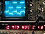
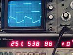
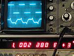
Here in a post from some years ago is an SH-50 at a meter in a living room, a square wave at 250, 1K and 2.5KHz, square wave in, mic sig on scope. These also radiate as a single source, the sources sum coherently and do not produce an interference pattern (lobes and nulls).
http://www.diyaudio.com/forums/multi-way/71824-making-square-waves-2.html
The driving need for our business was to make all the sources combine acoustically in a coherent way is so that one can radiate as if it were one source with a much larger acoustic power. When you do that, the sound spectrum is not only constant with left or right position but in depth as well (sans hf absorption at large distances) because one has satisfied the distances needed to add coherently into a single spherical segment of radiation over a wide band.
If you do not have constant directivity, then the spectral balance changes strongly with location (think line array outdoors) and inhomogeneous radiation causes the sound to change moving side to side or when the wind blows as well.
Hey, you like big sound, I have not done the square wave test with these, but they should reproduce one over an even broader band.
Two will do a 40,000 seat stadium nicely, four in a large stadium like the second link. With headphones, you can get sort of an idea what it sounds like to have one uniform source though. They went back and measured later, they were 700 feet at the far point.
http://www.facebook.com/pages/Danley-Sound-Labs-Inc/126113687424773?ref=ts
Big stereo, I kept thinking, they really need to show movies here.
http://blog.mixonline.com/briefingr...ty-to-brigham-young-university-football-fans/
Best,
Tom Danley


") With the advent of digital loudspeaker management, I was able to time align all the drivers and cabinets in the array, which I'm sure helps quite a bit.
With the advent of digital loudspeaker management, I was able to time align all the drivers and cabinets in the array, which I'm sure helps quite a bit.