Dispelling ground myths

jkeny

Industry Expert, Member Sponsor
Feb 9, 2012
3,374
42
383
Ireland
The title refers to this 2007 presentation by Henry Ott called "Audio interconnections & grounding - dispelling the myths"

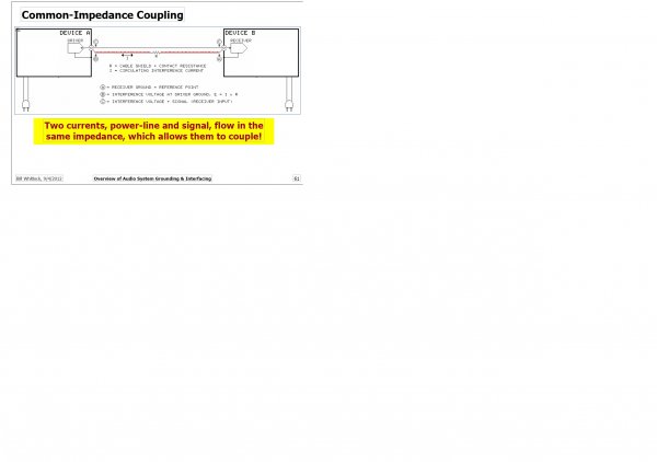
There is also another useful presentation, this time from 2012 by Bill Whitlock "An overview of Audio system grounding & interfacing"


I thought it worthwhile to start this thread as it applies to many discussions on this forum which involve grounding issues

So if you read both of these presentations you will see that there are a great number of considerations & aspects to electrical noise intrusion in audio devices which are interconnected.

Different considerations & approaches apply depending on the frequency of the noise & there is no hard boundary to this. In there words high frequency currents return to source via the path of least impedance whereas low frequency currents return via path of least resistance. This sounds simple but what defines high frequency Vs low frequency & is there a grey area in the middle where return currents will behave in either/both ways?

This is a well known rule in pcb design & it is easy to implement in most cases - assuming a solid ground plane on the bottom layer of a two layer pcb design, the HF currents return will be a roughly mirror image, on the ground plane, of the signal track on the top layer. It will not be as defined as the signal track but rather a statistical spread of return current with the highest density of current mirroring the shape of the signal track but also less density of current return pathways spreading out from this.

So here's a couple of diagrams to explain this:
First a simple U shaped traced over a ground plane
successful_pcb_grounding_fig9.jpg

The measured return current for a 1Khz signal - color coded to show density of return current. As can be seen almost all the return current flows directly across the ground plane from A to D
successful_pcb_grounding_fig10.jpg

The measured return current for "intermediate" frequency signal
"shows current for a 50kHz signal flowing primarily along the signal trace (the wide green line following the path of the trace) and, to a lesser extent, directly from load to source (the fainter, wide, green line from the two ends of the trace) and in between. The middle area is light blue and not dark blue, indicating minimal current flow."
successful_pcb_grounding_fig11.jpg

And finally return current for HF signal 1MHz - Virtually all the return ground current is flowing along the path of the signal trace.
successful_pcb_grounding_fig12.jpg

So what's all this got to do with interconnecting audio devices?
This is the first principle of return currents - that different frequencies behave differently
So what happens when it's cables carrying signal & return currents between devices?

Just as an aside there are two considerations:
- what is the configuration to get the best, optimal audio environment for our interconnected audio devices?
- what is the best way to achieve optimal measurements when characterising a device & is this the same as above?

We can have device connection configurations which don't reveal any audible issues but when measured will show some measured noise.

More in following posts if there's any interest?
 

RogerD

VIP/Donor
May 23, 2010
3,734
319
565
BiggestLittleCity
There have been many articles written about correct internal grounding of digital processing. http://www.ti.com/lit/an/spra501/spra501.pdf

https://www.diodes.com/assets/App-Note-Files/AN011-P.pdf

On the subject of what amount of chassis grounding is necessary to remove all the common mode noise in a audio system,I have seen nothing on the subject. In my experience to squeeze the most SQ out of a bonded chassis scheme the pathway must be larger than what is currently considered adequate for the requirement.
 

Folsom

VIP/Donor
Oct 25, 2015
6,029
1,501
550
Eastern WA
Common mode is a mixed bag with safety ground. Lowering the resistance of it can lower some common mode noise that had a path through circuity. However it also can increase common mode noise that was already taking a path to safety ground (while doing misdeeds along the path).

What is it you want to know about common mode? I use DENO Schurter's and common mode chokes (CMC's) to reduce a lot of it. It gets more complicated with circuitry that isn't just the power input & safety ground.

To be honest I'm not sure what Jkenny's post has to do with the "environment" aka cables, I guess. That's basically just a demonstration in how AC follows the path of least inductance. We don't have ground planes between our cables. I don't think this is anything more than a call for not using high inductance cables, at this point.
 

jkeny

Industry Expert, Member Sponsor
Feb 9, 2012
3,374
42
383
Ireland
There have been many articles written about correct internal grounding of digital processing. http://www.ti.com/lit/an/spra501/spra501.pdf

https://www.diodes.com/assets/App-Note-Files/AN011-P.pdf

On the subject of what amount of chassis grounding is necessary to remove all the common mode noise in a audio system,I have seen nothing on the subject. In my experience to squeeze the most SQ out of a bonded chassis scheme the pathway must be larger than what is currently considered adequate for the requirement.

One of the reasons I made the distinction in my post above between the different pathways back to source that different frequencies tend towards, is that when it comes to discussing cables & interconnects between devices we no longer have a nice pcb model to deal with - we have a mixture of lots of different considerations.

So let's see where this leads?

Here's what Whitlock says:
The BIG Problem with Unbalanced
• When two devices, each having its own power cord, are connected by an audio cable, a small power-line current will flow in the audio cable … a fact of life
• Essentially all this current flows in the grounded conductor, typically the “shield” of audio cables
• Since this conductor has resistance, a noise voltage appears over its length … per Ohm’s law
• The noise voltage is directly added to the signal seen at the receiver … just like two batteries in series
common impedance coupling.jpg
Technically, this coupling mechanism is called “common-impedance coupling” because an impedance (resistance) is “common” (shared) to two circuits. One circuit is between device A output and device B input (the signal circuit) and the other is between the AC power connections at each device. In this example, since there are no safety ground connections, the current in the second circuit is due to “leakage current” (which flows from power-line to chassis in each device). The “common impedance” is, of course, the resistance of the grounded conductor (usually, but not always, the shield) in the interconnect cable.
Leakage Current Effect.jpg
The “parasitic capacitance” in each device causes a small AC current to flow. Just as with a battery, current must flow into a capacitor to increase the voltage across it – or “charge” it. Conversely, current must flow out of a capacitor to decrease the voltage across it – or “discharge” it. Since these capacitors connect to the 120 VAC 60 Hz AC power, the voltage across them is constantly changing and a predictable amount of AC current will flow in the process. For equipment with UL listing and a 2-prong AC power connection, this current can be no higher than 0.75 mA – just enough to cause a slight tingling sensation if it flows in your body. Although harmlessly low, this current can cause enough voltage drop over the length of the signal interconnect cable to add significant “buzz” to the audio. While it’s remotely possible that leakage current could cause a “hum bar” issue in video, this author has never seen or heard of such a case.

Now what Whitlock doesn't say above is that there are always leakage currents (except in battery supply PSes) - it's just a matter of what current level - Typical leakage current limits by application are:
Information technology

Permanently connected – 3.5 mA or more in some applications
Movable or pluggable, not handheld – 3.5mA
Handheld – 0.25 mA
medical grade PS permissible leakage current under normal conditions is 0.5mA and 1mA

Class I Equipment:
Must have a protection against the electric shock by means of a basic insulation in combination with a protective earth ground connected to the equipment case.- maximum leakage current is 0.75 mA for the hand held and 3.5mA for the other equipment.

Class II equipment:
These equipment do not have a protective earth ground. Such equipment uses reinforced or double insulation to provide protection against the electric shocks. Maximum leakage current is 0.25 mA.

Now Whitlock goes on to calculate the reduction in SNR due to half the 0.75mA allowed on a shield resistance of 1 ohm
"• Signal to Noise ratio = 20 x log (316 mV?316 µV) = 60 dB
• This is 35 dB worse than an audio CD!"
Readers can work out what SNR would result from twice this amount of current leakage.

What he also doesn't mention are computer SMPS such as seen in this video of noise from a Dell laptop due to it SMPS power block see here & how ground lift kills this noise. This can often be felt in a laptop if you put it on your bare legs & a ground metal part is in contact with your leg - a tingling sensation. (BTW, anybody who suggest that an SMPS is in a plastic case such as a Meanwell brick & therefore can't be grounded demonstrates exactly how little they know about this)

He also doesn't mention USB cables & their usually weak ground & shielding

So note on the diagram the chassis of both devices is part of the route of this leakage current.

What happens when we connect a low impedance cable between chassis?
 

Attachments

  • common impedance coupling.jpg
    common impedance coupling.jpg
    218.9 KB · Views: 413
Last edited:

jkeny

Industry Expert, Member Sponsor
Feb 9, 2012
3,374
42
383
Ireland
Common mode is a mixed bag with safety ground. Lowering the resistance of it can lower some common mode noise that had a path through circuity. However it also can increase common mode noise that was already taking a path to safety ground (while doing misdeeds along the path).

What is it you want to know about common mode? I use DENO Schurter's and common mode chokes (CMC's) to reduce a lot of it. It gets more complicated with circuitry that isn't just the power input & safety ground.

To be honest I'm not sure what Jkenny's post has to do with the "environment" aka cables, I guess. That's basically just a demonstration in how AC follows the path of least inductance. We don't have ground planes between our cables. I don't think this is anything more than a call for not using high inductance cables, at this point.

Maybe you missed what I said in my first post ?
So what's all this got to do with interconnecting audio devices?
This is the first principle of return currents - that different frequencies behave differently
So what happens when it's cables carrying signal & return currents between devices?
 

RogerD

VIP/Donor
May 23, 2010
3,734
319
565
BiggestLittleCity
One of the reasons I made the distinction in my post above between the different pathways back to source that different frequencies tend towards, is that when it comes to discussing cables & interconnects between devices we no longer have a nice pcb model to deal with - we have a mixture of lots of different considerations.

So let's see where this leads?

Here's what Whitlock says:


Now what Whitlock doesn't say above is that there are always leakage currents - it's just a matter of what current level - Typical leakage current limits by application are:
Information technology

Permanently connected – 3.5 mA or more in some applications
Movable or pluggable, not handheld – 3.5mA
Handheld – 0.25 mA
medical grade PS permissible leakage current under normal conditions is 0.5mA and 1mA

Class I Equipment:
Must have a protection against the electric shock by means of a basic insulation in combination with a protective earth ground connected to the equipment case.- maximum leakage current is 0.75 mA for the hand held and 3.5mA for the other equipment.

Class II equipment:
These equipment do not have a protective earth ground. Such equipment uses reinforced or double insulation to provide protection against the electric shocks. Maximum leakage current is 0.25 mA.

Now Whitlock goes on to calculate the reduction in SNR due to half the 0.75mA allowed on a shield resistance of 1 ohm
"• Signal to Noise ratio = 20 x log (316 mV?316 µV) = 60 dB
• This is 35 dB worse than an audio CD!"
Readers can work out what SNR would result from twice this amount of current leakage.

What he also doesn't mention are computer SMPS such as seen in this video of noise from a Dell laptop due to it SMPS power block see here & how ground lift kills this noise. This can often be felt in a laptop if you put it on your bare legs & a ground metal part is in contact with your leg - a tingling sensation.

He also doesn't mention USB cables & their usually weak ground & shielding

So note on the diagram the chassis of both devices is part of the route of this leakage current.

What happens when we connect a low impedance cable between chassis?

The common mode noise would couple. Wouldn't this be bonding each piece of gear...much like in a rack mount. The entire circuit would need to be connected to earth ground.
 

jkeny

Industry Expert, Member Sponsor
Feb 9, 2012
3,374
42
383
Ireland
Same stuff from Henry Ott
Common Impedance coupling 2.jpg

SCIN reduce.jpg

so what I believe RogerD is achieving is a reduction in this Shield Current Induced Noise (SCIN) for low frequency shield currents (<500KHz):
- Reduce ground potential differences by adding a heavy gauge parallel earth connection

Exactly what RogerD is doing using a low impedance strap between the chassis of devices - dealing with these LF currents
 

jkeny

Industry Expert, Member Sponsor
Feb 9, 2012
3,374
42
383
Ireland
The common mode noise would couple. Wouldn't this be bonding each piece of gear...much like in a rack mount. The entire circuit would need to be connected to earth ground.
CM noise itself is not the problem - it's interfering with signal return currents that is - avoiding this is easier said than done
 
Last edited:

RogerD

VIP/Donor
May 23, 2010
3,734
319
565
BiggestLittleCity
CM noise itself is not the problem - it's interfering with signal return currents that is - easier said than done

I can see where SCIN would be a major contributor to degrading the audio signal. That's the main difference between cables I believe.
All this can be mitigated by chassis grounding. Many will dispute,but until you actually star ground the chassis adequately,a person can't say I'm wrong.
 

jkeny

Industry Expert, Member Sponsor
Feb 9, 2012
3,374
42
383
Ireland
I can see where SCIN would be a major contributor to degrading the audio signal. That's the main difference between cables I believe.
All this can be mitigated by chassis grounding. Many will dispute,but until you actually star ground the chassis adequately,a person can't say I'm wrong.

Yep, I'd agree!

Well chassis grounding or "heavy gauge parallel earth connection", as Ott calls it can provide a preferred return pathway for currents <500KHz, according to Ott
That does leave considerations about HF current noise, though.
 

LL21

Well-Known Member
Dec 26, 2010
14,421
2,513
1,448
very very cool reading. thanks gents!
 

RogerD

VIP/Donor
May 23, 2010
3,734
319
565
BiggestLittleCity
Yep, I'd agree!

Well chassis grounding or "heavy gauge parallel earth connection", as Ott calls it can provide a preferred return pathway for currents <500KHz, according to Ottx
That does leave considerations about HF current noise, though.

In my experience once you chassis ground adequately,whatever is not returned to ground is of no consequence. The signal ground is tied to the chassis anyway,so a star circuit by chassis is all that is necessary.
 

jkeny

Industry Expert, Member Sponsor
Feb 9, 2012
3,374
42
383
Ireland
In my experience once you chassis ground adequately,whatever is not returned to ground is of no consequence. The signal ground is tied to the chassis anyway,so a star circuit by chassis is all that is necessary.

Yea, experience is not to be sniffed at & often reveals more than theory predicts
Theory predicts that current noise frequencies above 500KHz will be more likely to return via other pathways - just what those pathways may be & whether it affects signal ground should be considered
 

Folsom

VIP/Donor
Oct 25, 2015
6,029
1,501
550
Eastern WA
Meh. I can reject more noise with a different device that gets inserted inbetween the signal chain; break ground loop, plummet ground noise & cm.

Increasing the size of the safety ground reduces SCIN, but can also add parasitics elsewhere. For that reason I recommend some traditional forms of treatment that can reduce the overall amount of noise within the system to begin with. The most harmful sources from in on the AC cord, where as what's in the air is marginal barring RF generators (I mean literal ones). Well made gear isn't typically too susceptible to noise induction from stuff around it. I know people that separate out their cords so they don't touch but it so far has shown to either expose problems in their gear, or be diminishing returns x1000. I think getting cords off carpet might be about as far as one need truly go under decent conditions.

I would caution anyone trying to reduce SCIN by going wild with the ground conductor of an SE cable. I never recommend different sized gauges of wire, and hate coaxial. The benefits don't outweigh the sound. Simple twisted pair has the best overall balance between current, LCR, noise attenuation, and field suppression. Quad may work as well, but it's a mixed bag due to ga size, so it depends on application, generally prefer them for speaker cables.

jkenny, you're second post was all relevant. I don't think most can or need to make the connection to the first one. It doesn't really explain parasitics or anything. Most people have no idea what a ground plain is or what inductance actually means... and why that matters with AC.
 

jkeny

Industry Expert, Member Sponsor
Feb 9, 2012
3,374
42
383
Ireland
Meh. I can reject more noise with a different device that gets inserted inbetween the signal chain; break ground loop, plummet ground noise & cm.

Increasing the size of the safety ground reduces SCIN, but can also add parasitics elsewhere.
Can you expand on this, please?
For that reason I recommend some traditional forms of treatment that can reduce the overall amount of noise within the system to begin with. The most harmful sources from in on the AC cord, where as what's in the air is marginal barring RF generators (I mean literal ones). Well made gear isn't typically too susceptible to noise induction from stuff around it. I know people that separate out their cords so they don't touch but it so far has shown to either expose problems in their gear, or be diminishing returns x1000. I think getting cords off carpet might be about as far as one need truly go under decent conditions.

I would caution anyone trying to reduce SCIN by going wild with the ground conductor of an SE cable. I never recommend different sized gauges of wire, and hate coaxial. The benefits don't outweigh the sound. Simple twisted pair has the best overall balance between current, LCR, noise attenuation, and field suppression. Quad may work as well, but it's a mixed bag due to ga size, so it depends on application, generally prefer them for speaker cables.
Again, can you expand on this, please?
jkenny, you're second post was all relevant. I don't think most can or need to make the connection to the first one. It doesn't really explain parasitics or anything. Most people have no idea what a ground plain is or what inductance actually means... and why that matters with AC.
Oh, thank you :)
 

Folsom

VIP/Donor
Oct 25, 2015
6,029
1,501
550
Eastern WA
If the impedance is less because of the increased ground wire size, it becomes a path for more current that previously had another path. You divide noise into it. I can't say for all equipment, but there's plenty of noise parasitics from anything remotely near the chassis, often. The question is, was the path it took through some circuitry? Did it change the complex impedance negatively because it had a new place to go instead of being coupled? It's really a comment about the design of a device. Because of unknowns like that, my approach is not to use very large ground wires or try to make it act like a drain. It may work very well with some equipment, and terrible on others. As a designer it just isn't very practical to take a gamble when I can make something with no gamble.

That doesn't really begin to cover resonances, which is a ball game no one typically wants anything to do with at all.

As far as different sized gauges on wires, my subjective experience is it's always negative. It might, at times, benefit some stereos. It depends a lot on how much current flows, and how symmetric it is in nature with how the equipment works. But in general you can generate some noise. Here's an easy way to get an idea; take a powercord and add an extra 12ga neutral wire. Now use it for your DAC or whatever. You'll hear it! (obviously AC cords are not the same as interconnects, but it does demonstrate on a much larger scale what can happen)
 

RogerD

VIP/Donor
May 23, 2010
3,734
319
565
BiggestLittleCity
Meh. I can reject more noise with a different device that gets inserted inbetween the signal chain; break ground loop, plummet ground noise & cm.

Increasing the size of the safety ground reduces SCIN, but can also add parasitics elsewhere. For that reason I recommend some traditional forms of treatment that can reduce the overall amount of noise within the system to begin with. The most harmful sources from in on the AC cord, where as what's in the air is marginal barring RF generators (I mean literal ones). Well made gear isn't typically too susceptible to noise induction from stuff around it. I know people that separate out their cords so they don't touch but it so far has shown to either expose problems in their gear, or be diminishing returns x1000. I think getting cords off carpet might be about as far as one need truly go under decent conditions.

I would caution anyone trying to reduce SCIN by going wild with the ground conductor of an SE cable. I never recommend different sized gauges of wire, and hate coaxial. The benefits don't outweigh the sound. Simple twisted pair has the best overall balance between current, LCR, noise attenuation, and field suppression. Quad may work as well, but it's a mixed bag due to ga size, so it depends on application, generally prefer them for speaker cables.

jkenny, you're second post was all relevant. I don't think most can or need to make the connection to the first one. It doesn't really explain parasitics or anything. Most people have no idea what a ground plain theis or what inductance actually means... and why that matters with AC.
How can you reject more noise, when the nose is produced internally? Ferrite rings,blockers,EMI rejection materials don't work either. Granted a well designed cable can make a difference,but that's not a total problem solver. I have read many like comments but only a adequate parallel ground circuit will make a profound difference. The rest is just incremental and that is what the high end makes it's living on.
 

jkeny

Industry Expert, Member Sponsor
Feb 9, 2012
3,374
42
383
Ireland
If the impedance is less because of the increased ground wire size, it becomes a path for more current that previously had another path. You divide noise into it. I can't say for all equipment, but there's plenty of noise parasitics from anything remotely near the chassis, often. The question is, was the path it took through some circuitry? Did it change the complex impedance negatively because it had a new place to go instead of being coupled? It's really a comment about the design of a device. Because of unknowns like that, my approach is not to use very large ground wires or try to make it act like a drain. It may work very well with some equipment, and terrible on others. As a designer it just isn't very practical to take a gamble when I can make something with no gamble.
Can you give some examples of actual detrimental results from this chassis grounding approach, please as I can't relate to what you say?

The thing is that RogerD isn't designing equipment - he & others have done aftermarket adjustments with, it seems, great audible improvement.
I agree if one has carte blanche & designing from ground up then these adjustments should not be needed for the device you have full design control over but you may be forgetting that your audio device usually has to be connected to other devices & this is maybe where things don't go as planned

That doesn't really begin to cover resonances, which is a ball game no one typically wants anything to do with at all.

As far as different sized gauges on wires, my subjective experience is it's always negative. It might, at times, benefit some stereos. It depends a lot on how much current flows, and how symmetric it is in nature with how the equipment works. But in general you can generate some noise. Here's an easy way to get an idea; take a powercord and add an extra 12ga neutral wire. Now use it for your DAC or whatever. You'll hear it! (obviously AC cords are not the same as interconnects, but it does demonstrate on a much larger scale what can happen)
What is the cause of this extra noise(?) from the larger gauge neutral wire?
 

jkeny

Industry Expert, Member Sponsor
Feb 9, 2012
3,374
42
383
Ireland
jkenny, you're second post was all relevant. I don't think most can or need to make the connection to the first one. It doesn't really explain parasitics or anything. Most people have no idea what a ground plain is or what inductance actually means... and why that matters with AC.

Just to clarify what I was intending - my first post showed that, depending on frequency, return currents take different paths back to source - low frequencies (<500KHz) tend towards the path of least resistance; high frequencies tend to follow the path of least impedance. This is the behaviour whether on pcb or cables. Obviously, this has relevance to cables & to parallel earth connections in audio device performance & in audio device measurements.

I posted elsewhere, this article from the Audio Precision knowledgebase in which they recommend, for optimal measurements, a star grounding scheme for such ground strapping.
"Recommended Test System Grounding"
Question:
What kind of grounding is best to use between the various devices in my test system?

Answer:
When integrating instruments, accessories, and DUTs (devices under test) into a test and measurement system, observing good grounding practice is always important in achieving optimal measurement results. Small ground potential differences between devices in the test system (such as switchers, accessories, the DUT, and the test instrument) can couple into the signal path and cause undesirable interference or noise due to the inherent stray capacitance between signal conductors and the chassis. To prevent this problem, Audio Precision strongly recommends connecting the chassis ground of each device directly to the ground of the test instrument via wires having as low an impedance as possible. This technique is often referred to as “ground bonding” or “chassis bonding.”

Star grounding
Diagram of analyzer in center with grounds radiating out to the switchers.
star-ideal.png
"Audio Precision strongly recommends connecting the chassis ground of each device directly to the ground of the test instrument via wires having as low an impedance as possible. This technique is often referred to as “ground bonding” or “chassis bonding.”

Bus grounding
Diagram of ground from analyzer to first switcher, and then daisy-chaining all the others.
bus-grounding.png
"We do not recommend bus grounding (daisy chaining), where several devices are serially connected to a low-impedance conductor called a “ground bus.” The resistance in each leg of the chain puts the devices at different ground potentials, and is not as effective as star grounding.

Combination Star/Bus
Diagram of grounds radiating from analyzer to four switchers, and then a small jumper from each to another switcher.
star-w-bond.png
When the serial links are very short, the combination star/bus grounding configuration can simplify connections while providing good grounding performance.


CAB-BOND Kit
switchers.png


Making Grounding Cables

Alternatively, you can make your own ground cables. These must be very low-impedance, heavy gauge copper wire, as short as possible for the application, and terminated with large surface area low-impedance spade lugs. If the lugs are a crimp type, make sure to use the proper crimping tool to ensure a secure, gas-tight connection. Fasten the one end of the lug to the switcher with a large, truss head screw. Attach the other end to one of the ground posts on the front of the analyzer.

And just a note for some people who read these recommendations from Ap & say "doh, what an idiot, our SMPS is plastic so no grounding can be done" - show some semblance of intelligence - does it really need to be spelled out what you should do or maybe you have to contact AP but beware they will think you are an idiot for asking such a dumb question - they certainly won't believe they are talking to an E'ee.
 
Last edited:

Speedskater

Well-Known Member
Sep 30, 2010
941
15
368
Cleveland Ohio
reference stuff, part 1:

Grounding Systems

SRPP :: System Reference Potential Plane
STGP ::
Signal Transport Ground Plane
ZSRG :: Zero Signal Reference Grid
ZSRG :: Zero Signal Reference Conductors
ZSRP :: Zero Signal Reference Potential
ZSRP :: Zero Signal Reference Plane
MESH-CBN :: Meshed Common Bonding Network
MESH-IBN :: Meshed Isolated Bonding Network
PEC :: Paralleled Earth Conductors
PBC :: Paralleled Bonding Conductors

Although Keith Armstrong prefers to call them:
Conductive Structures
 

About us

  • What’s Best Forum is THE forum for high end audio, product reviews, advice and sharing experiences on the best of everything else. This is THE place where audiophiles and audio companies discuss vintage, contemporary and new audio products, music servers, music streamers, computer audio, digital-to-analog converters, turntables, phono stages, cartridges, reel-to-reel tape machines, speakers, headphones and tube and solid-state amplification. Founded in 2010 What’s Best Forum invites intelligent and courteous people of all interests and backgrounds to describe and discuss the best of everything. From beginners to life-long hobbyists to industry professionals, we enjoy learning about new things and meeting new people, and participating in spirited debates.

Quick Navigation

User Menu

Steve Williams
Site Founder | Site Owner | Administrator
Ron Resnick
Site Co-Owner | Administrator
Julian (The Fixer)
Website Build | Marketing Managersing