Analogue playback Wander

jkeny

Industry Expert, Member Sponsor
Feb 9, 2012
3,374
42
383
Ireland
OK, I will briefly address this. You are painting an imaginary scenario with an arbitrary difference built into it. There is no justification for either one. The analog one for example could also have "sudden" jumps due to bearing of a platter. Or snaps of the rubber belt. The digital one also has slew limiting and won't all of a sudden jump from one value to another value that is too large. On and on.
The differences are not arbitrary but reflect the origin of the speed/timing variations - one is mechanical in nature & the other comes from the resonating of a crystal slice when excited electrically. No amount of examples (snapping of rubber band, doh!) will change the essential difference between these. As I said - one is a macro phenomena & the other a micro one. If analogue were actually comprised of samples we would have many samples all being affected in the same way with speed variations whereas digital samples are individually affected in random ways - substantially different

But we don't care about any of this detail as we can measure the two systems and compare them. And such a measurement shows that both systems have random modulation of their speed in a similar manner at low frequencies. This is backed by my last post explaining that CLT will give us similar distribution when the contributions are many and random in nature.
Yes we do care about the detail as that is crucial & comparing a summarised/statistical distribution of their randomness does not give us the correct view into how we hear this difference

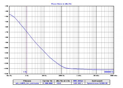
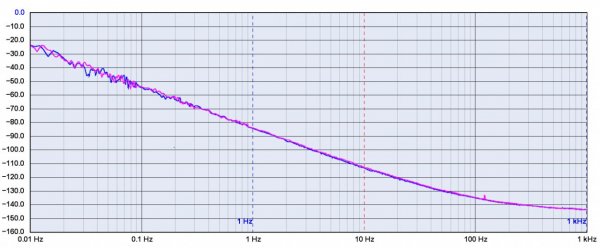
The measurements show that the levels of the same distortion in analog is orders of magnitude higher than digital. There is nothing that makes that "more nice" than the same distortion type in digital. Here is another paired comparison using different instrumentation. First is a turntable measured by HiFi News:
.....................
If you want to counter any of this, you need to show measurements that capture those differences. What you describe would absolutely show up in objective measurements.
You already have my analysis & you just keep repeating the same point/ same measurements as if I hadn't already stated that summarised statistical distribution is no indication of what we hear & the differences that are perceived.
 

amirm

Banned
Apr 2, 2010
15,813
38
0
Seattle, WA
The differences are not arbitrary but reflect the origin of the speed/timing variations - one is mechanical in nature & the other comes from the resonating of a crystal slice when excited electrically.
Your second statement about digital is wrong but it doesn't matter. Whatever the cause is not important. It is the effect that we hear. And can measure. Psychoacoustics + controlled listening tests explains both scenarios. Words of disagreement as you keep expressing is neither here, nor there.
 

jkeny

Industry Expert, Member Sponsor
Feb 9, 2012
3,374
42
383
Ireland
Your second statement about digital is wrong but it doesn't matter. Whatever the cause is not important as I have shown.
Well it does matter & is important.
It is the effect that we hear.
I agree! I & quite a few others can attest to the audible differences a clock with low close-in phase, can make.
And can measure.
I agree that measurements would be of interest but they need to be relevant & of sufficient sensitivity to reveal the phenomena under investigation. Anybody can do measurements which will reveal nothing & declare that there is therefore nothing to be heard
Psychoacoustics + controlled listening tests explains both scenarios. Words of disagreement as you keep expressing is neither here, nor there.
All objections that you have made to my analysis have been dealt with & shown to be flawed. I would say that it's your "Words of disagreement as you keep expressing is neither here, nor there"

I asked you before had you ever tried a clock with low close-in phase noise in any listening you have done & compared it to the same configuration with standard clock. I took it from your lack of an answer that you haven't but now's the time to correct this if I'm wrong
 

FrantzM

Member Sponsor & WBF Founding Member
Apr 20, 2010
6,455
29
405
Jkenny

In many discussions you participate it has become customary for you to have the last word, no matter what. I do not expect a different behavior or outcome to this post.

Here is the thing. You come up with graphs showing effects that are real and measurable. You do claim their audibility but the amount of proof is as rare as a snowflakes in the Sahara desert in midday. You claim "You and others" have heard it and this seems to be your proof. There is no other way to describe this as anecdote, not a proof. Can you come up with some peer-reviewed research that support your view or do we need to accept your conjectures as the Godspell? Some seem to find this satisfactory, I don't.
I am bowing out unless you come with facts to support your views. IN which case I will learn something new and thank you in advance for it , else those are conjectures and it is a case of using data to lead to preferred results. Hardly scientific and too often disingenuous.

Peace
 

amirm

Banned
Apr 2, 2010
15,813
38
0
Seattle, WA
I asked you before had you ever tried a clock with low close-in phase noise in any listening you have done & compared it to the same configuration with standard clock. I took it from your lack of an answer that you haven't but now's the time to correct this if I'm wrong
I don't remember seeing the question. I ignore a lot of what you write....

The answer is a resounding yes. I had a USB to S/PDIF converter that had a switch between its high performance clock and a poor one. So in this regard, it was, far worse scenario than you describe.

I flipped the switch from poor to great quality and immediately heard an improvement. Warmer, more liquid sound. More analog like. I felt vindicated that there was something to this jitter business.

I then closed my eyes, flipped a few times at random and then tried to identify said clock. No luck. No matter how many times I tried, I would frequently get it wrong and pick the poor clock as the better one, or find that I could not tell the difference.

I took the device to work and did the AB for a couple of guys there. Both thought I was crazy expecting them to hear a difference.

Now your turn. How did you do this comparison?
 

jkeny

Industry Expert, Member Sponsor
Feb 9, 2012
3,374
42
383
Ireland
I don't remember seeing the question. I ignore a lot of what you write....

The answer is a resounding yes. I had a USB to S/PDIF converter that had a switch between its high performance clock and a poor one. So in this regard, it was, far worse scenario than you describe.

I flipped the switch from poor to great quality and immediately heard an improvement. Warmer, more liquid sound. More analog like. I felt vindicated that there was something to this jitter business.

I then closed my eyes, flipped a few times at random and then tried to identify said clock. No luck. No matter how many times I tried, I would frequently get it wrong and pick the poor clock as the better one, or find that I could not tell the difference.

I took the device to work and did the AB for a couple of guys there. Both thought I was crazy expecting them to hear a difference.

Now your turn. How did you do this comparison?

Right, I recognise the Audiophileo from your description - right?
If so then the clock phase noise as posted on their website isn't considered low close-in phase noise
Audiophileo clock phase noise.jpg


The clock I used is almost exactly what Mike (Mivera) on ASR has posted
phase noise.jpg

As you can see close-in phase noise on my clock is far better than the Audiophileo one - @10Hz it's ~10dB better; @1Hz it's 15dB better; @ 0.1Hz it's 20dB better

Secondly, this is what they say on the Audiophileo site about their "jitter simulator"
To get an idea how various levels of jitter influence sound quality, simply enable the JitterSimulator feature on the Audiophilleo1. When set to Level 1, the firmware adds roughly 250 ps RMS period jitter, and around 1300 ps RMS phase jitter integrated from 1 Hz to 100 kHz. These levels are typical for mid-range USB- S/PDIF interfaces, and on a higher-end system, it should be easy to hear their effects.

This is adding random jitter - the most benign as far as audibility is concerned.

And finally this is a USB to SPDIF converter so you are outputting SPDIF to a DAC with SPDIF receiver which uses a PLL - known to add it's own jitter.

In essence, if you are using the Audiophileo as I suspect, then I wouldn't say you listened to a low close-in phase noise clock in a configuration that would allow you to hear the difference.

I used my own DAC which uses battery power (no leakage currents), which is also correctly isolated from USB (on the USB input, not after the USB receiver chip), has the clock sitting right next to the DAC chips I2S input pins & reclocks these signals at this point
The listening was done with two DACs - both exactly the same except for the clock & it was easily recognised as better sounding with the better clock.
Didn't need a blind test as I only use blind testing when I'm unsure of the audible differences

You do seem to report lots of differences that went away when you went to blind listening - an interesting phenomena!
 
Last edited:

microstrip

VIP/Donor
May 30, 2010
20,807
4,700
2,790
Portugal
Jkenny

In many discussions you participate it has become customary for you to have the last word, no matter what. I do not expect a different behavior or outcome to this post.

Here is the thing. You come up with graphs showing effects that are real and measurable. You do claim their audibility but the amount of proof is as rare as a snowflakes in the Sahara desert in midday. You claim "You and others" have heard it and this seems to be your proof. There is no other way to describe this as anecdote, not a proof. Can you come up with some peer-reviewed research that support your view or do we need to accept your conjectures as the Godspell? Some seem to find this satisfactory, I don't.
I am bowing out unless you come with facts to support your views. IN which case I will learn something new and thank you in advance for it , else those are conjectures and it is a case of using data to lead to preferred results. Hardly scientific and too often disingenuous.

Peace

Frantz,

I have avoided taking part in this debate, as I am not an expert in jitter, but have been reading it with interest. And I think I must bring here the old words of John Curl

"Finally I stopped measuring and started listening, and I realized that the capacitor did have a fundamental flaw. This is where the ear has it all over test equipment. The test equipment is almost always brought on line to actually measure problems the ear hears. So we’re always working in reverse. If we do hear something and we can’t measure it then we try to find ways to measure what we hear. In the end we invariably find a measurement that matches what the ear hears and it becomes very obvious to everybody. "


If the tens, even hundreds, of great audio designers were still waiting for the peer-reviewed research with the listening tests we would not have the modern high-end sound quality and a forum debating what is the best. IMHO John brings new information to this forum, I appreciate it, as other manufacturers or developers are not interested in openly debating the knowledge on these matters they incorporate in their SOTA equipment.

But yes, this aggressive sword-play is tiresome.
 

jkeny

Industry Expert, Member Sponsor
Feb 9, 2012
3,374
42
383
Ireland
Frantz,

I have avoided taking part in this debate, as I am not an expert in jitter, but have been reading it with interest. And I think I must bring here the old words of John Curl

"Finally I stopped measuring and started listening, and I realized that the capacitor did have a fundamental flaw. This is where the ear has it all over test equipment. The test equipment is almost always brought on line to actually measure problems the ear hears. So we’re always working in reverse. If we do hear something and we can’t measure it then we try to find ways to measure what we hear. In the end we invariably find a measurement that matches what the ear hears and it becomes very obvious to everybody. "


If the tens, even hundreds, of great audio designers were still waiting for the peer-reviewed research with the listening tests we would not have the modern high-end sound quality and a forum debating what is the best. IMHO John brings new information to this forum, I appreciate it, as other manufacturers or developers are not interested in openly debating the knowledge on these matters they incorporate in their SOTA equipment.

Thanks Micro
Just in reply to Frantz - I don't expect him to accept anything I say as gospel - I don't take anyone's report as true unless I have experienced it myself. What I am doing is reporting what I have hear (I'm not alone) & with this thread, was trying to tease out what perceptual mechanism might be responsible for what I hear. I might be wrong about the mechanism of operation but by discussing it I find it helps me stress test my thinking.
 
Last edited:

amirm

Banned
Apr 2, 2010
15,813
38
0
Seattle, WA
The listening was done with two DACs - both exactly the same except for the clock & it was easily recognised as better sounding with the better clock.
Didn't need a blind test as I only use blind testing when I'm unsure of the audible differences
 

amirm

Banned
Apr 2, 2010
15,813
38
0
Seattle, WA
Thanks Micro
Just in reply to Frantz - I don't expect him to accept anything I say as gospel - I don't take anyone's report as true unless I have experienced it myself. What I am doing is reporting what I have hear (I'm not alone) & with this thread, was trying to tease out what perceptual mechanism might be responsible for what I hear. I might be wrong about the mechanism of operation but by discussing it I find it helps me stress test my thinking.
You want to stress test your thinking? Have someone else do the switching for you. I assure you the obvious things you think you are hearing will disappear like a fart in the wind....
 

Don Hills

Well-Known Member
Jun 20, 2013
366
1
323
Wellington, New Zealand
... You must not have understood what I posted before - speed variations in TT platters cause the full frequency spectrum to be shifted by the timing variation at a particular point in time. So let me ask you this does a sample timing error (caused by clock jitter) cause that only sample to be mistimed or the full frequency spectrum to be mistimed & shifted? See the difference? ...

The full frequency spectrum is "mistimed and shifted" by a sample timing error, just as it is in the case of turntable "wow". To prove this, consider the sample time variation required to produce "close-in phase noise". Go really close in, such as about 0.5 Hz. The clock variation steadily increases for half a second, then steadily decreases back to the correct timing for half a second, then repeats but in the other direction. In frequency terms, the clock increases and decreases in frequency over a full cycle of 2 seconds. It's the same effect as a 33 RPM turntable once per revolution "wow". It might not sound quite the same if it were bad enough to be audible, because the turntable wow is usually periodic (in other words, a 0.5 Hz "tone"), whereas phase noise is just that - noise, so it will manifest as a somewhat irregular "rumble".
The maths remain the same as you increase the frequency / rate of the timing / speed variations. However, the audible perception does vary - at very low frequencies, the wow/jitter is perceived as a frequency /speed variation. As the rate/frequency increases, it starts to be perceived as new signals in the audible spectrum - "sidebands". By the time you get up to your single sample variations, the new signals are up around the Nyquist rate and above hearing range.

But all of this is straining at gnats, because in any competent DAC the variation in sample-to-sample timing is so small that the effects on the analogue signal output are inaudible. They're orders of magnitude smaller than the variations in timing of a good turntable, which themselves are mostly inaudible. So you might want to widen your search for the cause of the differences you believe you hear.
 

jkeny

Industry Expert, Member Sponsor
Feb 9, 2012
3,374
42
383
Ireland
Don, I certainly don't understand jitter in the way you do - I believe you are very wrong in your understanding. Can't elaborate as I'm using phone
 

jkeny

Industry Expert, Member Sponsor
Feb 9, 2012
3,374
42
383
Ireland
I can use my computer again

The full frequency spectrum is "mistimed and shifted" by a sample timing error, just as it is in the case of turntable "wow". To prove this, consider the sample time variation required to produce "close-in phase noise". Go really close in, such as about 0.5 Hz. The clock variation steadily increases for half a second, then steadily decreases back to the correct timing for half a second, then repeats but in the other direction. In frequency terms, the clock increases and decreases in frequency over a full cycle of 2 seconds. It's the same effect as a 33 RPM turntable once per revolution "wow". It might not sound quite the same if it were bad enough to be audible, because the turntable wow is usually periodic (in other words, a 0.5 Hz "tone"), whereas phase noise is just that - noise, so it will manifest as a somewhat irregular "rumble".
This is so fundamentally wrong, I don't know where to start? Let's go back to what jitter is - it's the deviation of the CLOCK EDGE from its correct position in time. You really can't believe that for phase noise @ 0.5Hz that all the clock edges begin to increase in variability for half a second & then this variability decreases for 0.5seconds? That would mean that they aren't random but are interconnected. This is contrary to all known understanding of clock jitter
The maths remain the same as you increase the frequency / rate of the timing / speed variations. However, the audible perception does vary - at very low frequencies, the wow/jitter is perceived as a frequency /speed variation. As the rate/frequency increases, it starts to be perceived as new signals in the audible spectrum - "sidebands". By the time you get up to your single sample variations, the new signals are up around the Nyquist rate and above hearing range.
Your understanding of jitter is wrong & therefore everything you say about the maths is incorrect - wrong premise, wrong conclusions
 
Last edited:

Robh3606

Well-Known Member
Aug 24, 2010
1,480
468
1,155
Destiny
Would like to know what oscillator that is as it is exemplary for close in phase noise but I see PS anomalies at 6/120/180Hz & wonder how you can possibly produce such a plot with a PS intrusion such as this - something badly amiss with your plot - can you name the oscillator & do you have an Allan Variance plot for it?

Hello jkeny

There is nothing wrong with the plot and those are not power supply anomalies. So you don't fully understand the measurement so you criticize it and say something is amiss? That is noise pick-up when the measurement was done from the radiated 60Hz line and the harmonics. You see them all the time in this type of measurement. I will see if I can find the Allan Variance but Short Term Stability: 1E-13/1 sec.

Rob:)
 

jkeny

Industry Expert, Member Sponsor
Feb 9, 2012
3,374
42
383
Ireland
Hello jkeny

There is nothing wrong with the plot and those are not power supply anomalies. So you don't fully understand the measurement so you criticize it and say something is amiss? That is noise pick-up when the measurement was done from the radiated 60Hz line and the harmonics. You see them all the time in this type of measurement. I will see if I can find the Allan Variance but Short Term Stability: 1E-13/1 sec.

Rob:)

I saw that 60Hz 20dB spike & other harmonic spikes & wondered how you can measure such a low phase noise. You don't plot <1Hz - why? Thanks for the short term stability figure - nothing below 1sec? Again, can you to name this oscillator as I asked before? - is it a standard oscillator we would see in an audio device or an oven controlled one? That shelf from 20Hz to 1Khz suggests a PLL might be involved - is it?

Some further details would be welcome

You seem to know something about clocks so you will know that the close-in phase noise stage of this slope is caused by flicker noise of the crystal & this simple equation 1/f (f being the frequency) is the mathematical expression for flicker noise - as we get closer to 0Hz the phase noise rises with a slope that is the reciprical of frequency.

Anyway, as I said already this is not addressing the rise in the slope of the skirt seen in FFTs which I was talking about here - "My contention is that the energy 2Hz away from the signal spike would be very much higher - I would hazard <-50dB down from the main signal energy."
You disagreed with this & showed the phase noise plot of a very good clock to counter, in some way, what I said?
 
Last edited:

Don Hills

Well-Known Member
Jun 20, 2013
366
1
323
Wellington, New Zealand
... This is so fundamentally wrong, I don't know where to start? Let's go back to what jitter is - it's the deviation of the CLOCK EDGE from its correct position in time.

"In signal processing, phase noise is the frequency domain representation of rapid, short-term, random fluctuations in the phase of a waveform, caused by time domain instabilities ("jitter").[1] Generally speaking, radio frequency engineers speak of the phase noise of an oscillator, whereas digital system engineers work with the jitter of a clock." - Wikipedia.
So turntable wow and flutter is indeed jitter.

You really can't believe that for phase noise @ 0.5Hz that all the clock edges begin to increase in variability for half a second & then this variability decreases for 0.5seconds? That would mean that they aren't random but are interconnected. This is contrary to all known understanding of clock jitter

They are interconnected, but the variability doesn't increase and decrease. The variation increases and decreases. All the clock edges progressively move one way relative to the correct time, then move the other way.

Your understanding of jitter is wrong & therefore everything you say about the maths is incorrect - wrong premise, wrong conclusions

You've painted yourself into a corner here. Explain how you can have "close in phase noise" without the frequency variation of the clock containing the components. For example, for phase noise in your "2 to 5 Hz" range, the noise must contain components in the 2 to 5 Hz range. Put in phase terms, the clock timing variations must exhibit long-term periodicity relative to the clock period. The math holds all the way down to DC, which of course is simple "clock drift".

One way of looking at jitter is, as the Wikipedia definition said, as random variations in frequency. Imagine that the clock oscillator has a tuning knob that will vary the frequency slightly up or down - like the pitch control on some turntables. Now imagine randomly twirling the knob back and forth. That's jitter.
 

jkeny

Industry Expert, Member Sponsor
Feb 9, 2012
3,374
42
383
Ireland
"In signal processing, phase noise is the frequency domain representation of rapid, short-term, random fluctuations in the phase of a waveform, caused by time domain instabilities ("jitter").[1] Generally speaking, radio frequency engineers speak of the phase noise of an oscillator, whereas digital system engineers work with the jitter of a clock." - Wikipedia.
So turntable wow and flutter is indeed jitter.


They are interconnected, but the variability doesn't increase and decrease. The variation increases and decreases. All the clock edges progressively move one way relative to the correct time, then move the other way.
The highlighted statement is what I was saying was fundamentally wrong. How can the timing be RANDOM & yet this statement hold true? This implies that there is a connection between the mistimings (all moving in one direction) rather than them arising from the flicker noise of the atomic structure of the crystal slice. Again this is what is fundamentally wrong in your understanding of jitter

You've painted yourself into a corner here. Explain how you can have "close in phase noise" without the frequency variation of the clock containing the components. For example, for phase noise in your "2 to 5 Hz" range, the noise must contain components in the 2 to 5 Hz range. Put in phase terms, the clock timing variations must exhibit long-term periodicity relative to the clock period. The math holds all the way down to DC, which of course is simple "clock drift".
This is the problem that I mentioned already - looking at FFTs can easily lead one's thinking astray - an FFT is a statistical summary of the energy found in the bin frequencies used in the FFT - if a particular bin (like 2-5Hz) has a high energy it will plot as a hill rising out of the floor - it doesn't mean that the clock edges progessively move towards 2Hz & then away from 2Hz, it simply means that over the time measured in the FFT there was more energy found in the 2-5Hz bin than outside it - the oscillator was found to be mistiming in the 2-5Hz range more than 6-9Hz but not en mass as you state - it's purely statistics & nothing to do with the clock's edges all moving one way & then all moving another way.

If you had a dice which was rigged to bias towards a six & you threw it 1000 times, you would see six was the statistically favoured face that showed but in the throwing you wouldn't notice any "moving towards six" when looking at the individual throw.

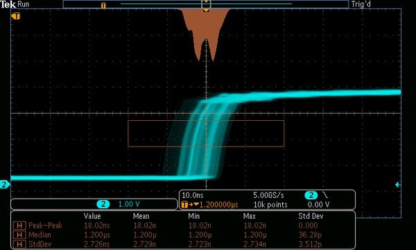
This diagram should help - it shows a scope shot of the rising edge of a waveform plotted over many cycles & overlaid on top of one another - each individual scope trace would be seen as a solid single line tracing the rising edge but when we overlay multiple such events, instead of a thin solid rising line in the trace we see a broadened trace meaning that the rising edge is not always happening at the same time, it is varying. In the scope trace we see two areas of this broadened trace which are brighter than the surrounding areas - this signifies that there are more lines being traced in these areas than in other, less bright areas - in other words the rising edge timing is wrong by this 2 offsets more than others - it doesn't mean that if we looked at the build up of this scope trace in serial time that we would see the scope trace moving into this region & the trace repeatedly falling in this region one after another for repeated runs & then moving away from this region - we would see no concerted move of the scope trace in this way - it looks random, just like the dice throw

The histogram in brown above the scope trace shows the waveform histogram of a rising edge showing the two peaks in the distribution of edge position (jitter) over time.
MDO3000-Oscilloscope-Datasheet--890270-24-L.jpg

One way of looking at jitter is, as the Wikipedia definition said, as random variations in frequency. Imagine that the clock oscillator has a tuning knob that will vary the frequency slightly up or down - like the pitch control on some turntables. Now imagine randomly twirling the knob back and forth. That's jitter.
Yes, but that's not what you described above - your description above suggests that the turning of the knob doesn't happen instantly & that there will be a concerted building of the timing edges towards the final knob position.

And this is the fundamental difference between WOW in analogue & wander in clocks - the WOW is the result of the platter speed ramping towards a wrong timing & then falling away - this is a speed change happening in serial time. Wander in clocks is NOT happening in this way - there's no 'ramping' - one clock tick might be off from the idealised clock, the rising edge happening too soon, the next clock tick rising edge could be too late - it's random - there's no connected timing differences between the clock edges as there is in the analogue WOW phenomena. The WOW in analogue has a mechanical origin & therefore is interconnected in this way, gradually moving towards & then away from the wrong speed. Totally different phenomena to clock jitter even though at a summary level they both look the same.

Remember I said that the summary view may be the same but that the underlying mechanisms can be different?

Does this lead to a different perception? Yes it does & trying to equate analogue WOW to clock jitter is fundamentally wrong in many ways!

Smokester on ASR shares my view too "let's hypothesize that the turntable deviations are due to variations in the rotational velocity of the platter. Then the deviations will be highly correlated because the inertia of the platter won't allow sudden (and random) changes from one end of the distribution to the other. Two sequential measurements (done at or above the Nyquist frequency) can't be very far apart. So they are correlated."
 
Last edited:

Don Hills

Well-Known Member
Jun 20, 2013
366
1
323
Wellington, New Zealand
The highlighted statement is what I was saying was fundamentally wrong. How can the timing be RANDOM & yet this statement hold true? This implies that there is a connection between the mistimings (all moving in one direction) rather than them arising from the flicker noise of the atomic structure of the crystal slice. Again this is what is fundamentally wrong in your understanding of jitter ...

You still don't get it. Maybe an example:

Take 10 clock ticks. Each number below is the time the tick occurs relative to the "correct" time. A positive number means the tick is late (clock slow) and vice versa for negative.
0 -1 +1 -2 0 +3 -2 0 +1 0
Phase noise / jitter, correct? And corresponding to relatively phase noise frequencies.
Now the same noise, but with a low frequency component:
0 0 +3 +0 +3 +6 +0 +2 +2 0
It's not obvious from that. or indeed from a waterfall display such as you posted a picture of, but there is half a cycle of LF noise in there:
0 +1 +2 +2 +3 +3 +2 +2 +1 0
In frequency terms, the clock slows down then returns to the correct speed over a 10 sample period.

That is exactly what happens in a jittery clock. And in fact it happens more often than not, because as the phase noise plots show, longer-term variations in clock timing occur more frequently than short term variations. So there is indeed a connection between the mistimings. They can indeed move in one direction.The most extreme example of this is where all the ticks come consistently early or late (the clock is running fast or slow.) It's exactly the same effect as turntable wow. The "pitch control" analogy applies exactly.

I hope I've made it clear enough for "those following along at home", so I'm done here unless anyone else has any questions or comments.
 

jkeny

Industry Expert, Member Sponsor
Feb 9, 2012
3,374
42
383
Ireland
You still don't get it. Maybe an example:

Take 10 clock ticks. Each number below is the time the tick occurs relative to the "correct" time. A positive number means the tick is late (clock slow) and vice versa for negative.
0 -1 +1 -2 0 +3 -2 0 +1 0
Phase noise / jitter, correct? And corresponding to relatively phase noise frequencies.
Now the same noise, but with a low frequency component:
0 0 +3 +0 +3 +6 +0 +2 +2 0
It's not obvious from that. or indeed from a waterfall display such as you posted a picture of, but there is half a cycle of LF noise in there:
0 +1 +2 +2 +3 +3 +2 +2 +1 0
In frequency terms, the clock slows down then returns to the correct speed over a 10 sample period.
And this is exactly what I'm saying doesn't happen & you don't seem to get. There's no grouping of the timing in the manner you show - this wrong understanding is why you think it's the equivalent of analogue wow.. The clock timing is random but there is a bias towards closer in phase noise so if 10,000 sequential clock ticks are written out as you have done there will be no CONSECUTIVE sequence of mistimings that shows what you have shown, it will be random. BUT if you count up the number of random (not consecutive) times that the clock is offset by 2Hz you will find it is far higher than the number of times it is off by 1,000Hz for instance. This is what's shown in the J-test FFTs where the skirt shows the distribution over time of the frequency offset from correct frequency (signal spike)

That is exactly what happens in a jittery clock. And in fact it happens more often than not, because as the phase noise plots show, longer-term variations in clock timing occur more frequently than short term variations. So there is indeed a connection between the mistimings. They can indeed move in one direction.The most extreme example of this is where all the ticks come consistently early or late (the clock is running fast or slow.) It's exactly the same effect as turntable wow. The "pitch control" analogy applies exactly.

I hope I've made it clear enough for "those following along at home", so I'm done here unless anyone else has any questions or comments.
I think when you look back at this &/or ask others (although I've made it as clear as I can but you still reject the correction to your misunderstanding) you will see how wrong you are?

Do you think in the scope pic I posted above that you would see each individual trace consecutively fall into the same area i.e a grouping of consecutive traces towards this brighter area & then traces moving away from this area when viewed consecutively?

Again, think about why close-in phase noise is called flicker noise - it's thought to be the result of some event at the quantum level although this is not confirmed!

And if you look at that Wiki entry you will see that pink noise is the same as 1/f or flicker noise - it has a distribution with a power density of 1/f, exactly as close-in clock phase noise - there's no grouping of noise around 2Hz, then grouping around 3Hz, etc that gives rise to freq distribution seen in pink noise - it's random but with a particular frequency distribution described by 1/f - it's not the equivalent of analogue wow with a constantly changing pitch - it may look like that in a frequency distribution plot which is a summary over time but it isn't the same at the detail, non summary level
 
Last edited:

amirm

Banned
Apr 2, 2010
15,813
38
0
Seattle, WA
This diagram should help - it shows a scope shot of the rising edge of a waveform plotted over many cycles & overlaid on top of one another - each individual scope trace would be seen as a solid single line tracing the rising edge but when we overlay multiple such events, instead of a thin solid rising line in the trace we see a broadened trace meaning that the rising edge is not always happening at the same time, it is varying. In the scope trace we see two areas of this broadened trace which are brighter than the surrounding areas - this signifies that there are more lines being traced in these areas than in other, less bright areas - in other words the rising edge timing is wrong by this 2 offsets more than others - it doesn't mean that if we looked at the build up of this scope trace in serial time that we would see the scope trace moving into this region & the trace repeatedly falling in this region one after another for repeated runs & then moving away from this region - we would see no concerted move of the scope trace in this way - it looks random, just like the dice throw

The histogram in brown above the scope trace shows the waveform histogram of a rising edge showing the two peaks in the distribution of edge position (jitter) over time.

View attachment 32483
No. Just no. That scope is sampling at 5 Ghz. That is 5,000,000 Khz. Our audio bandwidth on a good day may be 50 Khz. Bandwidth limit that scope to 50 Khz and then come and show that kind of jitter.

Audio circuits do not have such slew rates as I explained earlier. The timing of the output of the DAC cannot and will not change instantaneously. If it did, it would be a step function and that would show up as odd harmonics of that step with bessel frequency coefficients.

This is why I keep saying you MUST measure the output of the DAC, not what goes into it. The turntable measurements I post are the final output of what comes out of the turntable. No one is showing you the component distributions to it which may indeed have step functions like you imagine for digital (but again, slew limited due to inertia of the mechanical system).

Let me repeat: the turntable measurements I post where for the final output of the system. You can't keep comparing that to what goes into the DAC. And with the wrong instrumentation with massive bandwidth to boot.
 

About us

  • What’s Best Forum is THE forum for high end audio, product reviews, advice and sharing experiences on the best of everything else. This is THE place where audiophiles and audio companies discuss vintage, contemporary and new audio products, music servers, music streamers, computer audio, digital-to-analog converters, turntables, phono stages, cartridges, reel-to-reel tape machines, speakers, headphones and tube and solid-state amplification. Founded in 2010 What’s Best Forum invites intelligent and courteous people of all interests and backgrounds to describe and discuss the best of everything. From beginners to life-long hobbyists to industry professionals, we enjoy learning about new things and meeting new people, and participating in spirited debates.

Quick Navigation

User Menu

Steve Williams
Site Founder | Site Owner | Administrator
Ron Resnick
Site Co-Owner | Administrator
Julian (The Fixer)
Website Build | Marketing Managersing