Cable Theory

DonH50

Member Sponsor & WBF Technical Expert
Jun 22, 2010
3,952
312
1,670
Monument, CO
Nice job, Amir!

FWIWFM, last time I fooled with cable simulations I used a distributed model (RLCG) with anywhere from 10 to 100 taps. It was easy to set up in the simulator as iterated instances, or in my Mathcad model as a transmission line model.

A lumped cable model typically puts the R first, then the L (though order doesn't matter), then the C at the load end where it has the most impact when driven by a low-impedance source (which describes most audio preamps/amps). It is thus a standard L model representation. I prefer a pi model myself, but with a low-Z source it doesn't make much difference. And, as I said above, I would (and do) use a much more distributed model for more realistic modeling, but in this case the simple model is easy for folk to understand and provides a gross (easy to see) means of visualizing the impact of various parameters.

The long way of saying I agree with gary and Amir re. the models in this instance. - Don
 

amirm

Banned
Apr 2, 2010
15,813
38
0
Seattle, WA
No, everything to the right of C1 (vertical) capacitor represents the model of the speaker. The cap and everything to the left represents the model of the speaker cable (sans the source all the way to the left).
 

andy_c

Well-Known Member
Sep 24, 2010
189
0
921
www.andyc.diy-audio-engineering.org
Amir, I noticed that your simulation used R and L both in the "hot" and return sides of the cable, yet the voltages you were probing were with respect to ground. To make the plots clearer, a good thing to do is use the LTspice "label node" feature (F4 function key), and label two nodes, say, "spkr_hot" and "spkr_rtn". Then, when probing, instead of just clicking on the node, you click and drag, creating a black "reference probe" which is then placed on the non-ground return side. The voltage expression being plotted in the above example would then be V(spkr_hot,spkr_rtn), which is equivalent to V(spkr_hot) - V(spkr_rtn). IOW, it's a difference-mode measurement. This also allows the reader to relate the node name on the graph to a label on the schematic so it's reasonably clear to the reader which nodes are being probed.

Also, there's some interesting measured cable data of the per-foot R, L and C of many real-world cables here and here.

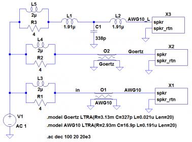
Another way of modeling the cable is with the SPICE LTRA ("lossy transmission line") model, supported by LTspice. It implements the Telegrapher's Equations directly, not only for AC, but for transient too. Here's an example of the usage with the Audioholics data from the Goertz cable and AWG10.

cable_sim_schem..jpg

This shows how LTRA is used, by placing .model statements in the sim and assigning those .model names to the LTRA element. For the Goertz .model statement, the example shows 20 feet of cable with 3.13 milliohms per foot, a very low 0.021 uH per foot, and an incredible 327 pF per foot. The boxes are subcircuits containing the Stereophile Kantor speaker model, which I can upload if you wish (.asc circuit file and .asy symbol file). The subcircuit approach makes multiple instances easy, to allow quick comparison of responses with different cables. The output impedance of the amplifier is modeled as 2 uH in parallel with 4 Ohms. This was obtained from amplifier schematics found on the Bryston site. This parallel RL circuit dominates the output impedance of a typical feedback solid-state amp.
 

amirm

Banned
Apr 2, 2010
15,813
38
0
Seattle, WA
Are you trying to create more work for me? :D

Seriously, I was confident that someone had done these things 10X better. And indeed, what you show above seems like a great way to do it. Are there different conclusions reached from that modeling and is there something we could do different to arrive at different data? If not, we can all follow that work.
 

andy_c

Well-Known Member
Sep 24, 2010
189
0
921
www.andyc.diy-audio-engineering.org
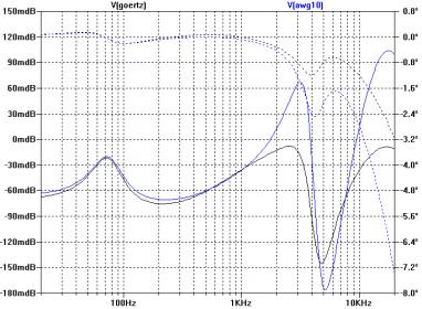
Here's the comparison data I got from this simulation. The Goertz had the lowest inductance and highest capacitance in the Audioholics tests, while the AWG 10 had the highest inductance and lowest capacitance. So these represent the extremes of the cables tested. The plot below is for 20 feet of cable.

awg10_vs_Goertz..jpg

Note the scale is in "milli-dB". My conclusion is the frequency response differences between these extreme cable examples is negligible.

BTW, the forum software took my above attachment, a 5 kB PNG file (lossless compression) that's larger and much easier to read, and making a small JPG file out of it (lossy compression, making it blurry). That JPG file is a bit larger than 30 kB.
 

terryj

New Member
Jul 4, 2010
512
0
0
bathurst NSW
ok, for the dummies.., err that would be me...interpretation time.

I may as well say what I THINK this is showing, then let others correct/expand.

First off, it looks like the speaker truly dominates. Tho there are differences, they at least follow the same general pattern, which led me to that conclusion.

The LHS gives us mdB, so it is a difference graph?? The right hand side, is that labeled degrees?

Let's take 3k, which is one of the biggest differences (apart from 17 k or thereabouts). The blue cable is roughly 70 m dB 'higher' than the black cable. Am I correct in saying that means the speaker will reproduce 3k 0.07 dB louder when using the blue cable?? Is that all I am seeing here??

That does not bode well for it being audible, and being rather sharp I feel would make it less audible than a more broad difference.

What info do we get from the right hand side?? And how does that info translate into hearing?

thanks.
 

andy_c

Well-Known Member
Sep 24, 2010
189
0
921
www.andyc.diy-audio-engineering.org
I may as well say what I THINK this is showing, then let others correct/expand.

First off, it looks like the speaker truly dominates. Tho there are differences, they at least follow the same general pattern, which led me to that conclusion.

Yes, that's right. A different speaker will give a different plot here.

The LHS gives us mdB, so it is a difference graph?? The right hand side, is that labeled degrees?

Yes, it's the difference in dB between the open-circuit voltage at the amplifier output and the voltage at the speaker. IOW, it's the frequency response contribution of the cable in dB (valid for this particular speaker, or rather, this speaker simulation only).

Let's take 3k, which is one of the biggest differences (apart from 17 k or thereabouts). The blue cable is roughly 70 m dB 'higher' than the black cable. Am I correct in saying that means the speaker will reproduce 3k 0.07 dB louder when using the blue cable?? Is that all I am seeing here??

Exactly right.

That does not bode well for it being audible, and being rather sharp I feel would make it less audible than a more broad difference.

This seems right. I'm not aware of any controlled experiments in which listeners were able to detect amplitude differences that small.

What info do we get from the right hand side?? And how does that info translate into hearing?

That's the phase shift as a function of frequency, in degrees, contributed by the cable, for this particular speaker load. It's not easily translated into audibility. I probably should have left it off.

Sorry about the poor legibility of the graph.
 

terryj

New Member
Jul 4, 2010
512
0
0
bathurst NSW
thanks for that andy.

Yes, that's right. A different speaker will give a different plot here.

Yep, understand that. Is there any 'significance' in what type of speaker was modelled here?? Is this on a bog standard cone speaker (ie nothing exotic). Would, say, a planar speaker be more profound?

You mentioned the audioholics, was theirs a sim too or real world.


Yes, it's the difference in dB between the open-circuit voltage at the amplifier output and the voltage at the speaker. IOW, it's the frequency response contribution of the cable in dB (valid for this particular speaker, or rather, this speaker simulation only).

Maybe therein lies the problem? A sim based on standard electrical theory may be enough for you, it certainly is for me, but for a cable guy?? Have there been any studies etc between how closely a sim matches real world?

This seems right. I'm not aware of any controlled experiments in which listeners were able to detect amplitude differences that small.

AFAIK, small amplitude differences are more detectable when very low Q, that these seem rather 'sharp' and so tiny, well....

That's the phase shift as a function of frequency, in degrees, contributed by the cable, for this particular speaker load. It's not easily translated into audibility. I probably should have left it off.

Sorry about the poor legibility of the graph.

Yeah, I'm a bit iffy on phase. What I mean is, what does it mean? Have no idea if this is true, but the 'only' thing about phase that ever stuck with me was something that mick malone (supratek) once said...'phase relates to the ambience we can hear'.

that is rather fluffy, and you gotta beware of what someone on the net says, but I kinda grabbed on to that. So I'd certainly be interested in views on this.

On a gut level I have managed to make that make sense to me, I can imagine the cues that tell us where things are (ie ambience) have a lot to do with phase relationship.
 

Robh3606

Well-Known Member
Aug 24, 2010
1,481
469
1,155
Destiny
Have any of you actually measured any interconnect cables?? I have measured a couple using CLIO and after looking at the measurements you have to wonder what the cable debates are all about. Looking at the cable measurements compared to say a typical speaker any influences from the cables look insignificant.

Rob:)
 

andy_c

Well-Known Member
Sep 24, 2010
189
0
921
www.andyc.diy-audio-engineering.org
Is there any 'significance' in what type of speaker was modelled here?? Is this on a bog standard cone speaker (ie nothing exotic). Would, say, a planar speaker be more profound?

It's meant to be a typical cone speaker. It is the same as the dummy load that Stereophile uses in their amplifier measurements. An electrostatic speaker might have a more pronounced effect. In the absence of a transformer, a single electrostatic driver will look capacitive (decreasing impedance with increasing frequency), but with a transformer there will be some frequency above which the impedance begins rising again. The capacitive nature of an electrostatic driver could make the series inductance of speaker cables more important when electrostatic speakers are used.

You mentioned the audioholics, was theirs a sim too or real world.

These were measurements I linked to earlier. These measurements can be found here and here.

Maybe therein lies the problem? A sim based on standard electrical theory may be enough for you, it certainly is for me, but for a cable guy?? Have there been any studies etc between how closely a sim matches real world?

Of course! One area in which transmission line theory plays a huge part is in defense systems such as radar. Because lives are at stake in such systems, huge amounts of testing are done. An aircraft radar might operate at a frequency of 10 GHz. That's 1 million times 10 kHz. Another way of looking at this is that the wavelength of the signal in a cable carrying that 10 GHz signal is one millionth of that at 10 kHz. There are instruments used for measuring parameters of cables and other devices to 100 GHz and beyond, called vector network analyzers. These can be and are used to check the measured results against the theoretical.

That said, the transmission line model used by the freeware LTspice and other SPICE simulators does not model the more esoteric parameters of transmission lines needed by the microwave engineer. For that there are specialized simulators that cost five figures and upward. I worked on one such simulator for a number of years. One of the tasks involved having a hardware vendor that was part of our team measure some devices with a vector network analyzer, and we had to figure out and fix any discrepancies between the transmission line models and their internal algorithms with experimental results.

Yeah, I'm a bit iffy on phase. What I mean is, what does it mean? Have no idea if this is true, but the 'only' thing about phase that ever stuck with me was something that mick malone (supratek) once said...'phase relates to the ambience we can hear'.

Well, I can't give you an intuitively palatable interpretation, just an interpretation of the mathematical results. If one knows both the magnitude and phase of the frequency response of a linear circuit, one can compute its step response. That's how the instrumentation that Stereophile uses to compute the step response of loudspeakers works internally. But because of the complexity of the math involved, it's non-trivial to be able to point to some phase glitch and say, "this will cause such-and-such a change in the step response". One must actually do the computation to find out.

As far as how this relates to perception of ambience and so on, acoustical wave effects (reflection, diffraction, etc.) will dominate here.
 

amirm

Banned
Apr 2, 2010
15,813
38
0
Seattle, WA
I like to extend the discussion to how can perform an A/B test using speaker cables. One of the issues I see with perceptions offered relative to speaker cable sound difference is the long time between when one cable is heard relative to another. Person plays a bunch of music with one, then a cable is removed, another is attached and then music is heard again. If we all agree that cable differences are small audibly, then it becomes super important to keep the switch over time very small. In my book, having it be a subset of a second is critical. As is going back to the original cable to make sure the difference is not because of how well the cable seats against the connectors. We also need to take care to have both cables be situated the same way and not move them mechanically.

All of this points to a hardware A/B system. It would require a linked set of boxes where both ends could be switched over at once. It is trivial to build one using relays and a button next to the observer that would force both to switch over at the same time.

I see some drawbacks to this test fixture:

1. The switching apparatus will impact the overall characteristics of the cable. How much I don't know. But let's say it is not zero. So if the outcome is that no difference is heard, would people accept the results or say that since the cable by itself was not used, the results are not valid? If people are not going to accept the results then there is no sense in running the test.

2. There may be some slight danger to the amp. Switching the line when music playing could cause the output stage of the amp to become unhappy and potentially damage the amp. If the switchover is fast as it should be, this is probably a non-issue but I don't want folks to go and try it and come complaining to me :).

While I am way too lazy to go and build this :D, how about you Gary? We are talking less than $50 worth of parts, giving us some real life data.

BTW, I will be happy at this stage with non-blind testing. Once we have that, then we can move to more rigorous testing.
 

mep

Member Sponsor & WBF Founding Member
Apr 20, 2010
9,481
17
0
What I am getting out of this thread is that the effect(s) of cables in our systems no matter what the design of the cables are is very insignificant electrically. If you look at the measurements, you would think there would be no audible differences. However, as Gary stated, he can easily hear differences between cables even though the measurements say it shouldn't be so. So, are we fooling ourselves (and if Gary really can pick out different cables blindfolded, that means something) or are we hearing things that we haven't devised measurements for yet?

I never heard of the two joints song before and got a laugh out of it. However, I'm missing the connection to this thread that Ron sees.
 

Steve Williams

Site Founder, Site Owner, Administrator
I like to extend the discussion to how can perform an A/B test using speaker cables. One of the issues I see with perceptions offered relative to speaker cable sound difference is the long time between when one cable is heard relative to another. Person plays a bunch of music with one, then a cable is removed, another is attached and then music is heard again. If we all agree that cable differences are small audibly, then it becomes super important to keep the switch over time very small. In my book, having it be a subset of a second is critical. As is going back to the original cable to make sure the difference is not because of how well the cable seats against the connectors. We also need to take care to have both cables be situated the same way and not move them mechanically.

All of this points to a hardware A/B system. It would require a linked set of boxes where both ends could be switched over at once. It is trivial to build one using relays and a button next to the observer that would force both to switch over at the same time.

I see some drawbacks to this test fixture:

1. The switching apparatus will impact the overall characteristics of the cable. How much I don't know. But let's say it is not zero. So if the outcome is that no difference is heard, would people accept the results or say that since the cable by itself was not used, the results are not valid? If people are not going to accept the results then there is no sense in running the test.

2. There may be some slight danger to the amp. Switching the line when music playing could cause the output stage of the amp to become unhappy and potentially damage the amp. If the switchover is fast as it should be, this is probably a non-issue but I don't want folks to go and try it and come complaining to me :).

While I am way too lazy to go and build this :D, how about you Gary? We are talking less than $50 worth of parts, giving us some real life data.

BTW, I will be happy at this stage with non-blind testing. Once we have that, then we can move to more rigorous testing.

when I visited Dave Wilson's house several years ago to compare the X-1 series 3 vs the X-2 he had a custom built switching box which was "neutral" . A wired switch was held by the listener at the listening position and pushing it resulted in immediate switching from one speaker to the other. All of the cables were otherwise identical and font end, amplification etc were identical. IOW switching lead to immediate listening of one speaker vs the other
 

amirm

Banned
Apr 2, 2010
15,813
38
0
Seattle, WA
when I visited Dave Wilson's house several years ago to compare the X-1 series 3 vs the X-2 he had a custom built switching box which was "neutral" . A wired switch was held by the listener at the listening position and pushing it resulted in immediate switching from one speaker to the other. All of the cables were otherwise identical and font end, amplification etc were identical. IOW switching lead to immediate listening of one speaker vs the other
Thanks Steve. Speaker selectors have existed forever. Since difference in speakers is much, much larger than cables, less objections are raised there. As you see from measurements of cables however, we are talking very small electrical differences here. So to the extent the switching gear causes the characteristics to change much more percentage wise, there will be more tendency to dismiss the results. For example, there is no question that if equiv. cable capacitance is 190 pf, there will be some change to that when the path goes through two more relays, two more connectors, two shorter wires inside of a box, closeness to power source and coil of the relay, etc.
 

amirm

Banned
Apr 2, 2010
15,813
38
0
Seattle, WA
What I am getting out of this thread is that the effect(s) of cables in our systems no matter what the design of the cables are is very insignificant electrically. If you look at the measurements, you would think there would be no audible differences. However, as Gary stated, he can easily hear differences between cables even though the measurements say it shouldn't be so. So, are we fooling ourselves (and if Gary really can pick out different cables blindfolded, that means something) or are we hearing things that we haven't devised measurements for yet?

I never heard of the two joints song before and got a laugh out of it. However, I'm missing the connection to this thread that Ron sees.
Let me see if I can clarify what is going on here.

It should not be surprising at all that electrical modeling of the cable shows little audible difference. After all, if it took me all of five minutes to run these simulations, the rest of the world would have also run it a million times before. And if this would would lead to knowing there are audible difference, then everyone would be on one side of the fence and not divided!

I would say the odds are very much against such analysis leading to any kind of proof that there are audible or significant differences. But let's look at our past history a bit in another space: digital interconnects.

There was a time when folks thought that if the S/PDIF digital audio stream is "digital" there would be no way two such cables could ever change the sound. The first time I heard people say there was a difference, I was one of the ones laughing at them just the same. Fast forward later and a bunch of people came forward presenting authoritative papers and math, showing that timing differences could be caused by the cable (i.e. jitter), resulting in significant impact to the resolution of audio signals. You don't get me to laugh anymore at the concept that S/PDIF cables could change what we hear.

So maybe something can be discovered. The first step in that is better understanding of the subject matter. That was what was required in above. Understanding the implicit clock in S/PDIF and how cable characteristics could change that. I thought Gary's original post got us the same thing: understanding what the cable does to the signal path.

The next step might be as I suggested. Getting better data as to whether the difference is audible. What is there right now can be so easily dismissed by the other side that we can't rely upon it.
 

Orb

New Member
Sep 8, 2010
3,010
2
0
What I am getting out of this thread is that the effect(s) of cables in our systems no matter what the design of the cables are is very insignificant electrically. If you look at the measurements, you would think there would be no audible differences. However, as Gary stated, he can easily hear differences between cables even though the measurements say it shouldn't be so. So, are we fooling ourselves (and if Gary really can pick out different cables blindfolded, that means something) or are we hearing things that we haven't devised measurements for yet?

I never heard of the two joints song before and got a laugh out of it. However, I'm missing the connection to this thread that Ron sees.

I would say it depends how you want to clarify the affect of cables in an active system, look back at my post #14 to see how this fits.
It is fair to say these issues are not part of the cable (example cleaning contacts often), however once you take a cable and plug it into the real world between two active components with various signal-chassis ground/galvanic isolation then it is in practical terms a combination of cable-electrical unit-power-oxidisation(dirty contacts,compromised,etc).

RCA is easier to consider as I am not entirely sure the complete interractions between amp-cable-speaker (including crossover-drivers) is fully understood, even Doug Self has theorised a bit on this.

However it should be possible to do a test that is applicable to both speaker and interconnects, but this requires instrumentation that can connect into the "chain" between the two active components or the amp and speaker, without adding isolation type affect, and importantly a musical note that is analysed in both time and frequency domain for each of the partials-harmonics up to 20khz IMO.
The test would not identify the mechanisms involved, just how or where the note is changed, however ideally this requires multiple notes taken at different points on the piano scale as an example.
Cheers
Orb
 
Last edited:

FrantzM

Member Sponsor & WBF Founding Member
Apr 20, 2010
6,455
29
405
Hi

mep points are very interesting. I know for a fact when I believed in the value of Cables. I call that period my "cable days", that all my opinions on cable where based on the cables I saw. never did I perform any comparison blinded. I did not need to ... It was "clear" that cables made a "huge" difference.... or so I thought ...

A few points to ponder:

One already has an idea of what the cable is purported to accomplish, via all the information available to an audiophile.
The look of the cable: A certain look convey an air of seriousness of knowledge of serious research. So the jacket is the thing. It must be fancy. The Transparent Audio Cable are formidable looking and tht dial on them ... ??? MAkes them look so different. I do find the piece of wood on the Nordost TopOdin Speaker cable silly TBH.
The physical dimension of the cable: A small cable will seem to "restrict" the lows but would seem to be better for the midrange if not the highs. If it is a power cable it must appear "big" to convey the sense of control it will yield on the system. It doesn't matter that the real wires not be that big, for example 10 AWG is not that big... two 10 AWG wires put together without their sheath/jacket are smaller in diameter than any pinky finger... 6 AWG is quite big but I have not yet seem any Audiophile power cord to use that size
Material: Copper would have a ..well.. more golden sound. warmer whereas Silver would signify lightness airy highs, not necessarily good bass .. So several, of course, expensive cables have a blend of copper and Silver or silver-plated copper... Perish the though to use Aluminum it is "clearly" an inferior metal.. I am waiting to see gold cables, they would be really too expensive, besides any audiophile worth its grain of salt knows the best electrical conductor is Silver followed by copper so ...
The packaging.. The more expensive the cable the more sophisticated the case in which it comes. A case which of course has absolutely no purpose other than ... I fail to see its purpose, since any carton would have been enough ..

All this to say that the power of suggestion must not be underestimated. Sighted we can tell the differences, unsighted, knowledge removed? Most audiophiles can't reliably ... Why would that be?
I often wonder what would be the reaction of audiophiles to the introduction of a cable in their system in which they don't see or know anything about the cable.. This has been played on occasions and in one of them which I find somewhat unethical .. It was reported that differences were heard when in reality the cables were not replaced ...
 

terryj

New Member
Jul 4, 2010
512
0
0
bathurst NSW
As I have always maintained, it is just down to human nature.

Very few of us are able to change our thoughts on a subject, no matter the rational arguments on that subject.

Once we have decided, that's that.

It's a bit like borrowing the book from the library, and some arrogant bugger has circled phrases and points eralier. (as if his opinions are important enought to be recorded for immortality). One thing we note from looking at the paragraphs circled (and his 'commentary' on them)...they either already agree or already disagree.

Same with audio discussions on the net. We will accept those posts/proofs that we already have, reject those that conflict.

It is rare indeed for people to be willing to learn, sad as that may be. (they do exist)

All of this points to a hardware A/B system. It would require a linked set of boxes where both ends could be switched over at once. It is trivial to build one using relays and a button next to the observer that would force both to switch over at the same time.

I see some drawbacks to this test fixture:

1. The switching apparatus will impact the overall characteristics of the cable. How much I don't know. But let's say it is not zero. So if the outcome is that no difference is heard, would people accept the results or say that since the cable by itself was not used, the results are not valid? If people are not going to accept the results then there is no sense in running the test.

I have done this, using relays powered remotely. It was a tad more than just speaker cables tho, we compared really old cdp and integrated amp and house wall wiring to top of the line modern cdp going to audiophile pre and class A amp with expensive ICs and speaker cable. Both were to the same common speaker set up.

Very little difference indeed, a few could NOT here any difference at all no matter how long they listened (45 mins or so), a few more could (eventually) start to hear differences between the 20 yr old cdp line and the $20 000 top end line, enough to decide they did prefer the expensive line...most agreed it took at least twenty minutes before they could get a handle.

All were 'amazed' at how damned close they were in sound.

Me? I flicked it a few times, laughed my head off that they were 'identical', and did not bother spending any time to fuss and worry over what are, in effect, trivial differences.

Same deal tho, after during the social part, with trhe beers and all going down, suddenly the differences started to grow!! It became easier (in a direct proportion to the amount of alcohol consumed*the time of discussion=ease of identification. Quite mathematical really!) The end result was that people settled back down to their previous positions on the matter!

Fascinating insight into the human beast.


Whilst I cannot test every single cable/speaker combination on the planet, it is sufficient for me that I can safely ignore cables (and the associated expense) in getting quality playback. I think that is the best any thread like this can do, lay out whatever data we have on the subject, and leave it to the individual to do with as he sees fit.

Does anyone really think the MLs experience changed anyones elses mind??

It's just a paragraph in the universal book of knowledge, to be circled and commented upon by the reader as he sees fit. And those comments are usually 'I already agree with this' or 'I already disagree with this'.

rare is the 'well, that argument changed my viewpoint or made me view things differently'.
 

About us

  • What’s Best Forum is THE forum for high end audio, product reviews, advice and sharing experiences on the best of everything else. This is THE place where audiophiles and audio companies discuss vintage, contemporary and new audio products, music servers, music streamers, computer audio, digital-to-analog converters, turntables, phono stages, cartridges, reel-to-reel tape machines, speakers, headphones and tube and solid-state amplification. Founded in 2010 What’s Best Forum invites intelligent and courteous people of all interests and backgrounds to describe and discuss the best of everything. From beginners to life-long hobbyists to industry professionals, we enjoy learning about new things and meeting new people, and participating in spirited debates.

Quick Navigation

User Menu

Steve Williams
Site Founder | Site Owner | Administrator
Ron Resnick
Site Co-Owner | Administrator
Julian (The Fixer)
Website Build | Marketing Managersing