Jitter is yet another one of those things not terribly hard to understand but with lots and lots of nuances and seemingly hidden details. To begin, let’s define some terms, starting with aperture time.
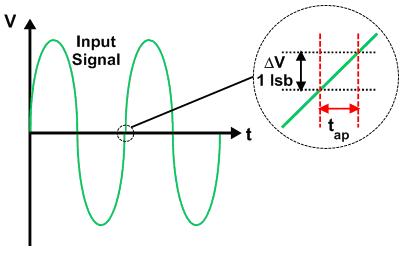
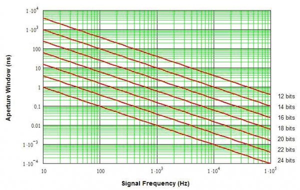
Figure 1 shows a signal we want to sample. It moves fastest (has the highest slew rate) at the center crossing. Zooming in, the time it takes the signal to change by 1 least-significant bit (lsb) in amplitude is the aperture time (tap). If we sample anywhere within this time window, the output will be the same code (assuming the amplitude starts and ends on a threshold). If we fall outside the window, the next code lower or higher will be output. For a sine wave of amplitude A and frequency f, the maximum slew rate is 2*pi*f*A (the magnitude of the first derivative with respect to time). For an N-bit ADC or DAC and that same sine wave input, the aperture time is 1/[(2^N)*pi*f] (the amplitude ratios out of the equation). Since it is the time required for the signal to pass through 1 lsb, the clock frequency (sampling rate) does not enter into the equation. Figure 2 shows the aperture time window for various frequencies and resolutions.
Time jitter is variation in the sampling time, which results in a corresponding change in sampled amplitude. Jitter that exceeds the aperture time causes the wrong codes to be output, reducing the ADC’s (or DAC’s) performance. The jitter can be random or deterministic (i.e. determined by some signal, be it the input, clock, power supply ripple, DSP, and/or some combination of those or other sources, including the radio transmitter down the road). Random normal (Gaussian) jitter with standard deviation equal to the aperture time causes about 8 dB reduction in SNR (a little over 1 bit of resolution loss).
Random jitter is just noise. It degrades (reduces) the SNR but does not add any nasty tones to the signal. It comes from three primary sources:
1. Thermal noise. Even just sitting there, the electronic particles in a resistor, wire, whatever are randomly moving around and bumping into each other. This creates noise, and the hotter it gets the farther and faster they move, creating even more noise. It is very broadband, extending (theoretically) into the THz (10^12) region. Real systems have filtering, intentional or not, that greatly limit the thermal noise bandwidth. This noise causes the sample time to vary a bit, and jitter is one result.
2. Ever look real closely at the water from a tap? It does not flow smoothly up close, even though from a couple of feet away it looks like a smooth stream. At any temperature above absolute zero, the electron flow that makes up current is not a steady stream, either. The electrons jump about randomly, in starts and stops, even though the overall trend is in one direction (at a given time). This is shot noise and happens whenever current flows. It is also very broadband.
3. The last noise source I’ll describe here is flicker noise, often called 1/f noise due to the 1/frequency characteristic it’s amplitude takes over much of it’s frequency range. (In fact, the slope can be 1/f^2, 1/f^3, etc. – and various combinations across the spectrum.) Flicker noise is caused by traps – places electrons (and holes) get “caught” and held by defects in materials (like wires, capacitors, resistors, etc.) The amount of time they get “held” varies and is random, but relatively long compared to other noise sources. This means it occurs primarily in the 1 to perhaps 10 Hz or so band for most audio components. (FETs are actually worse than bipolar transistors for flicker noise for various reasons a bit too esoteric to go into here.) While it can (and so it does) modulate the sampling circuits directly, it also causes phase modulation in the clock circuits (phase-locked loops, PLLs) used in data converter systems.
Deterministic jitter is much more insidious and I personally feel is the primary jitter component causing audible distortion. Deterministic means it is determined by some signal, and that is often not a signal we want in our system. These unwanted signals may not be related to the signal, and thus spurs from them really stand out to our ears. Even when related to the signal, deterministic jitter can reduce performance far more than random jitter by adding spurs that are much, much larger than simple random jitter (noise) adds. Examples will come later… First, a few causes:
1. Limited system bandwidth causes some deterministic jitter in all digital systems. In effect, limited bandwidth causes the sampling point to vary with the data (signal), adding signal-dependent deterministic jitter to our systems. Blah. I’ll come back to this one…
2. All real systems have a little bit of “memory” in them in the form of charge storage. This memory (hysteresis) can be stray (parasitic) capacitance or inductance, magnetic fields, etc. This tiny bit of memory means new signals coming in get corrupted a little bit by the previous signals, again introducing deterministic jitter into our systems.
3. Coupled signals are often the hardest to screen, identify, and fix. Any signal coupled into the clock creates deterministic jitter; that is, jitter determined by the coupled signal. Power supply ripple, the DSP clock in the AVR or CD/DVD/BRD player, the actual signal, external noise (radio/TV stations, cable amplifiers, the good buddy on his CB, etc.) can all sneak in through ground or power traces or even through the air to create deterministic jitter.
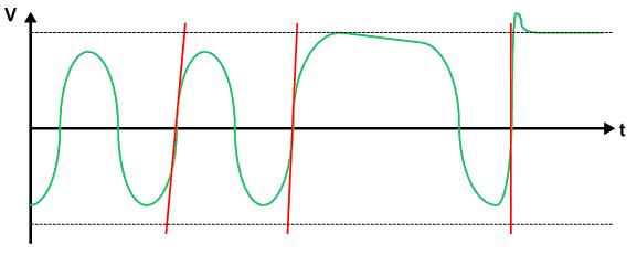
To get back to (1) briefly, look at Figure 3 below, which shows a few cycles in a digital bit stream. I have shown a […0,1,0,1,0,1,1,0,1…] pattern (sort of). Limited high-frequency bandwidth does not let the alternating 0/1 patterns reach full amplitude. If we look at the zero-crossing, where the data presumably changes, the slope is a little low (the red line is tilted a bit more) than the area where the signal has the 0,1,1 pattern and has time to reach full-scale. If we zoomed in very closely we’d see the crossing time is a little different for those two points due to the different slopes (which arise from the signal starting to transition from different levels).
Now, the top of the next (1,1) region is not flat; it slopes down a little bit. This indicates limited low-frequency bandwidth, i.e. it is not d.c.-coupled. For many reasons, wideband data systems are rarely d.c. coupled, and thus long strings of 1’s (or 0’s) can cause this to happen. The effect is again a slightly different crossing point because the signal starts from a different point, causing a different slope.
The last red line is on a part of the signal showing overshoot, where the signal actually shoots past the top and comes back down. Overshoot can improve the switching speed, but of course this means the edge is a little faster than the other edges, and again the center crossing is a little different. Aargh!
Before deciding all is lost, note that for digital signals these effects, while real, are rarely a problem in digital audio systems. The data rates are on the low end of what’s available, and error correction and careful signal construction (using tricks like dither to keep the signal always “busy”) results in extremely low bit error rates.
However, all these effects can affect the sampling clock, whether it is derived from the signal data stream (typical) or provided as a separate signal. Random and deterministic jitter on the ADC or DAC clock does cause real, measurable errors in the signals sent to our speakers. The audibility is often debated, of course; what a shock.
I am going to split the audio portion of this discussion into a separate thread. However, before leaving this one, I want to at least mention what it takes to do jitter measurement, if nothing else to explain why just asking somebody to measure it is often unfruitful. Audio jitter is fairly easy to measure because it is fairly large (10’s of ps to ns or more). Still, it takes some sophisticated equipment. At my workplace, measuring sub-ps (and into the fs) jitter requires clean low-jitter signal sources, pattern generators, digital sampling oscilloscopes (DSOs), and a host of filters, amplifiers, and specialized equipment that let us calibrate and compensate measurement error and extract (after much processing on a $2k computer running $10k to $100k of software) the true jitter numbers. We’re talking $100k signal sources, $250k bit error rate testers (BERTs), $150k and up DSOs, and $100k’s of extra amplifiers, cables, filters, and little black (gold, actually, often with heat sinks) boxes assembled into a complex test system. Perhaps $1M in equipment plus a few man-years of development. Your audio system is much lower frequency, of course, so maybe a mere $500k or so will get by…
Stay tuned for Part 2. - Don


